
The proliferation of intermittent energy sources, such as wind and solar photovoltaic generation, has introduced significant challenges to power system stability, primarily due to their inherent volatility and unpredictability. These resources typically do not participate in grid frequency regulation, leading to a growing scarcity of fast-responding frequency regulation resources as their penetration increases. The battery energy storage system (BESS), characterized by its rapid response speed and flexible configuration of power and energy capacity, presents a promising solution for enhancing grid frequency stability under these conditions. This article provides a comprehensive evaluation of the relative efficiency of BESS compared to conventional generation units (e.g., thermal and hydro) when participating in secondary frequency regulation. I will delineate the participation modes, establish a performance evaluation framework, and quantify the efficiency advantage through detailed dynamic simulations under various disturbance scenarios.
Introduction to Secondary Frequency Regulation and BESS Participation Modes
Secondary frequency regulation, or Automatic Generation Control (AGC), is responsible for restoring the system frequency to its nominal value and maintaining scheduled power interchanges between control areas following a disturbance. It corrects the residual frequency and tie-line power errors after primary frequency response. The key signal for secondary regulation is the Area Control Error (ACE), calculated as:
$$ ACE = \Delta P_{tie} + B \cdot \Delta f $$
where $$ \Delta P_{tie} $$ is the tie-line power exchange error, $$ B $$ is the frequency bias factor, and $$ \Delta f $$ is the frequency deviation.
The battery energy storage system can be integrated into the AGC framework through two principal signal-following modes, each with distinct control characteristics.
Mode 1: Participation Based on Direct ACE Signal Allocation
In this mode, the total ACE signal is directly partitioned between the conventional generation units and the battery energy storage system. The allocation coefficients are denoted as $$ \alpha $$ for the BESS and $$ \beta $$ for the conventional units, with $$ \alpha + \beta = 1 $$. The BESS receives its portion of the ACE signal ($$ \alpha \cdot ACE $$) as its power command and responds accordingly, working in tandem with the conventional units. This represents a proportional, or “droop,” type of response at the secondary control level. The dynamic model of a regional power grid incorporating a BESS in this mode is shown below.
The system dynamics can be described by the following key equations. The ACE signal is:
$$ S_{ACE} = ACE = \Delta P_{tie} + B \cdot \Delta f $$
The power contribution from the BESS is derived from a first-order lag model of its response:
$$ \Delta P_B(s) = \frac{\alpha \cdot S_{ACE}(s)}{s T_{BESS} + 1} $$
where $$ T_{BESS} $$ is the response time constant of the battery energy storage system. The conventional unit’s secondary frequency regulation output $$ \Delta P_S $$ is determined by its governor-turbine dynamics model $$ G(s) $$ and the allocated signal:
$$ \Delta P_S(s) = G(s) \cdot (\beta \cdot S_{ACE}(s)) $$
The system frequency deviation $$ \Delta F(s) $$ is governed by the swing equation:
$$ \Delta F(s) = \frac{1}{sM + D} \left( \Delta P_L(s) – \Delta P_P(s) – \Delta P_S(s) – \Delta P_B(s) \right) $$
where $$ M $$ is the inertia constant, $$ D $$ is the load damping coefficient, and $$ \Delta P_P $$ is the primary frequency response from all generators ($$ \Delta P_P = K_G \cdot \Delta F(s) $$, with $$ K_G $$ being the combined generator droop gain).
Mode 2: Participation Based on Area Regulation Requirement (ARR) Signal
The Area Regulation Requirement (ARR) is the output of the AGC’s integral controller, typically a PI controller acting on the ACE. The ARR signal is then allocated. In this mode, the BESS receives a fraction of the ARR signal ($$ \alpha \cdot ARR $$). Since the ARR is the integral of ACE, this mode inherently drives the ACE to zero, representing an integral-type response for the BESS at the secondary level. The control block diagram differs by placing the PI controller before the signal allocation.
In this configuration, the ARR signal is:
$$ S_{ARR}(s) = (K_P + \frac{K_I}{s}) \cdot S_{ACE}(s) $$
where $$ K_P $$ and $$ K_I $$ are the proportional and integral gains of the AGC controller. The BESS output is then:
$$ \Delta P_B(s) = \frac{\alpha \cdot S_{ARR}(s)}{s T_{BESS} + 1} $$
The conventional unit’s secondary response is:
$$ \Delta P_S(s) = G(s) \cdot (\beta \cdot S_{ARR}(s)) $$
The frequency dynamics equation remains structurally the same as in Mode 1, but with $$ \Delta P_S $$ and $$ \Delta P_B $$ now driven by $$ S_{ARR} $$.
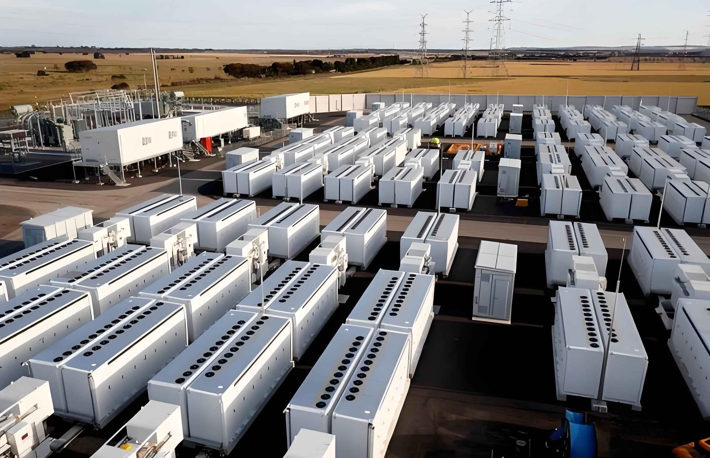
The visual representation of a modern battery energy storage system, which forms the core of this analysis, is provided below. Its fast-acting power electronics are key to its superior frequency response capabilities.
Comprehensive Performance Evaluation Index and Efficiency Assessment Methodology
To quantitatively compare the effectiveness of different frequency regulation resources, a comprehensive performance index is essential. I define several key metrics related to the dynamic response of system frequency:
| Metric Symbol | Description |
|---|---|
| $$ \omega_m $$ | Maximum frequency deviation (Hz) |
| $$ t_m $$ | Time at which $$ \omega_m $$ occurs (s) |
| $$ \omega_s $$ | Steady-state frequency deviation (Hz) |
| $$ t_s $$ | Settling time to reach $$ \omega_s $$ (s) |
| $$ V_m $$ | Frequency nadir rate ($$ V_m = \omega_m / (t_m – t_0) $$, Hz/s) |
| $$ V_r $$ | Frequency recovery rate ($$ V_r = (\omega_m – \omega_s) / (t_s – t_m) $$, Hz/s) |
| $$ \sigma_f $$ | Standard deviation of frequency deviation over the settling period. |
These raw metrics are normalized to a common scale and weighted to form a single Composite Performance Index (K):
$$
\begin{aligned}
\omega_m’ &= 1.0 + \frac{|\omega_m|}{\omega_n} \cdot k_1, \quad \omega_s’ = 1.0 + \frac{|\omega_s|}{\omega_n} \cdot k_2 \\
V_m’ &= 1.0 + \frac{|V_m|}{V_n} \cdot k_3, \quad V_r’ = 1.0 + \frac{|V_r|}{V_n} \cdot k_4 \\
\sigma_f’ &= 1.0 + \frac{\sigma_f}{f_n} \cdot k_5
\end{aligned}
$$
where $$ \omega_n, V_n, f_n $$ are base values (set to 50 Hz), and $$ k_1 $$ to $$ k_5 $$ are scaling coefficients (e.g., 5000, 1500, 500, -2500, 50) to bring the normalized values to a comparable order of magnitude. The composite index is then:
$$ K = a \cdot \omega_m’ + b \cdot \omega_s’ + c \cdot V_m’ + d \cdot V_r’ + e \cdot \sigma_f’ $$
with $$ a+b+c+d+e=1 $$. A lower K value indicates better frequency regulation performance. For step disturbances, weights are distributed across all metrics (e.g., a=0.2, b=0.2, c=0.1, d=0.1, e=0.4). For continuous random disturbances, the standard deviation is the most critical metric, so e is set to 1 and others to 0.
The efficiency multiple of the battery energy storage system is defined as the ratio of conventional generation capacity to BESS capacity required to achieve the same composite performance index K under identical disturbance conditions.
$$ \text{Efficiency Multiple} = \left| \frac{\text{Conventional Unit Capacity (MW)}}{\text{BESS Capacity (MW)}} \right|_{K \text{ is constant}} $$
The assessment procedure involves simulating three scenarios: 1) Regulation by conventional units only, 2) Joint regulation with BESS in ACE Mode, and 3) Joint regulation with BESS in ARR Mode. For a given disturbance, the capacity of the conventional units is adjusted in the joint regulation scenarios until the calculated K index matches the value from the “conventional units only” scenario. The efficiency multiple is then derived from this capacity ratio.
Simulation Analysis and Efficiency Quantification
I implemented the dynamic models in a simulation environment using parameters from a typical regional power grid, as summarized below.
| Parameter | Value |
|---|---|
| Total Load (PL) | 1000 MW |
| Conventional Unit Rating | 1000 MW |
| Inertia Constant (H, M=2H/PL) | 8.58 s |
| Load Damping Coefficient (D) | 2 pu MW/(pu Hz) |
| Generator Droop (1/KG) | 20 pu Hz/(pu MW) |
| Primary Frequency Regulation Capacity | ±80 MW (8% of PL) |
| Frequency Bias Factor (B) | 22 pu MW/(pu Hz) |
| BESS Response Time Constant (T_BESS) | 1 s |
| AGC PI Controller Gains (K_P, K_I) | Tuned for stable performance |
Case 1: Performance under Step Load Disturbance
A sudden load increase of 0.04 pu (40 MW) is applied. Initially, with a fixed BESS capacity of 1 MW/0.25 MWh and a fixed total conventional capacity, the joint regulation scenarios show superior performance (lower K index). To find the efficiency multiple, I then reduced the conventional capacity in the joint scenarios until the K index matched that of the “conventional only” case with full capacity.
The simulations revealed distinct response characteristics. In ACE Mode, the battery energy storage system provides immediate, aggressive power injection at the onset of the disturbance, significantly reducing the maximum frequency deviation ($$ \omega_m $$). Since the ACE signal decays as frequency recovers, the BESS output also reduces to zero. In ARR Mode, the initial BESS response is slightly less aggressive due to the integral controller’s lag, but it sustains its output for longer, driving the steady-state error to zero more decisively. The conventional units in the joint scenarios exhibit less pronounced “power reversal” overshoot compared to the “conventional only” case, demonstrating that the battery energy storage system alleviates stress on traditional generators.
The following table presents the capacity configurations and calculated efficiency multiples for different magnitudes of step disturbance.
| Disturbance (pu) | Regulation Scenario | Hydro Capacity (MW) | Thermal Capacity (MW) | BESS Capacity (MW) | Efficiency Multiple |
|---|---|---|---|---|---|
| 0.04 | Conventional Only | 10 | 30 | 0 | – |
| BESS (ACE Mode) | 10 | 18.2 | 1 | 11.8 | |
| BESS (ARR Mode) | 10 | 18.2 | 1 | 11.8 | |
| 0.08 | Conventional Only | 10 | 70 | 0 | – |
| BESS (ACE Mode) | 10 | 45.6 | 1 | 24.4 | |
| BESS (ARR Mode) | 10 | 45.6 | 1 | 24.4 |
Key Insight: Under step disturbances, the battery energy storage system demonstrates remarkably high efficiency, with multiples ranging from approximately 10 to 25. This means 1 MW of BESS capacity can replace 10-25 MW of conventional regulation capacity while maintaining the same frequency control quality as measured by the composite index K. The multiples are nearly identical for both ACE and ARR participation modes in this scenario. The efficiency tends to be more pronounced for larger disturbances within the simulated range, as the instant, full-power response of the BESS is more fully utilized.
Case 2: Performance under Continuous Random Disturbance
This case uses a 24-hour historical ACE time series from a real grid (sampled at 1-second intervals) as the continuous power disturbance input. This represents a more realistic and challenging AGC environment with persistent, random fluctuations. The goal is to maintain frequency within a tight band. A BESS with a power rating of 10 MW and 15-minute energy capacity is initially considered.
Simulations show that while the overall shape of the frequency deviation curve is similar across scenarios, the involvement of a battery energy storage system effectively clips the extreme peaks and troughs of frequency deviation due to its near-instantaneous response. This directly reduces the standard deviation of frequency ($$ \sigma_f $$), which is the critical metric (K index) for this case. The BESS output traces show almost vertical transitions, highlighting its superior ramp rate. In ACE Mode, the BESS acts like a high-bandwidth filter on the ACE signal. In ARR Mode, its action is smoother but slightly delayed.
To compute the efficiency multiple, I varied the capacity of the battery energy storage system and the mix of conventional units to achieve the same $$ \sigma_f $$ (and thus K index) as the “conventional only” base case. The results for different conventional fleet compositions are shown below.
| Conventional Fleet Mix (Hydro, Thermal) | BESS Participation Mode | BESS Capacity Required (MW) | Efficiency Multiple |
|---|---|---|---|
| 40 MW, 40 MW | ACE Mode | 6.81 | 5.88 |
| ARR Mode | 8.10 | 4.93 | |
| 20 MW, 60 MW | ACE Mode | 8.31 | 7.22 |
| ARR Mode | 9.88 | 6.07 | |
| 0 MW, 80 MW | ACE Mode | 8.03 | 7.47 |
| ARR Mode | 12.3 | 4.87 |
Key Insight: Under continuous random disturbances, the efficiency multiple of the battery energy storage system is significant but lower than in the step disturbance case, ranging from approximately 5 to 8 times. Notably, the participation mode has a clear impact. The ACE-based mode consistently shows a higher efficiency multiple (6-8) compared to the ARR-based mode (5-6). This is because the continuous, random nature of the ACE signal benefits from the direct, non-lagged response of the BESS in ACE Mode. The integral action in the ARR path introduces a slight delay, reducing the effectiveness per MW of BESS capacity in smoothing high-frequency components of the regulation signal.
Discussion and Conclusion
The analysis confirms the substantial efficiency advantage of battery energy storage systems in providing secondary frequency regulation. The quantified efficiency multiple depends on the nature of the grid disturbance and the chosen performance metric.
- For large, infrequent step disturbances (e.g., generator trips), the battery energy storage system can be 10-25 times more effective than conventional generation per MW of capacity. This is primarily due to its sub-second response and ability to deliver full rated power instantly, which is crucial for arresting frequency nadir.
- For the more typical, continuous random disturbances handled by AGC, the battery energy storage system is 5-8 times more efficient. Its value lies in its precise tracking capability, which smooths frequency deviations and reduces the wear and tear on conventional plants caused by constant ramping.
- The choice of participation mode matters. The direct ACE allocation mode generally yields a higher efficiency multiple, especially for continuous regulation, as it avoids the phase lag introduced by the AGC’s integral controller. The ARR mode may be preferred when strict, unbiased long-term signal tracking is the priority, albeit at a slightly lower effective efficiency.
The battery energy storage system is not merely a replacement but a force multiplier for existing frequency regulation resources. Integrating even a modestly sized battery energy storage system can dramatically enhance the overall responsiveness and performance of the regulation fleet. These findings provide a robust, simulation-based rationale for system planners and market operators to value and incentivize the participation of battery energy storage systems in frequency regulation ancillary services. The efficiency multiples derived here offer critical input for cost-benefit analyses and optimal resource portfolio decisions in modern power grids with high renewable penetration.