
The widespread deployment of Lithium Iron Phosphate (LFP) batteries in grid-scale energy storage systems is driven by their advantages in cycle life, cost-effectiveness, and relative safety. However, the inherent safety risks associated with lithium-ion chemistry cannot be overlooked. In the context of energy storage power stations, battery cells are densely packed into modules, which are then assembled into larger units called battery clusters within enclosed containers. This high-density configuration, combined with large energy capacities, presents a significant safety challenge: the thermal runaway of a single module, if not contained, can propagate to neighboring modules, potentially leading to catastrophic failure of the entire cluster. Among various triggers, overcharging represents a critical electrical abuse scenario that can initiate thermal runaway, especially considering potential failures in Battery Management System (BMS) state-of-charge (SOC) estimation due to cell aging, inconsistencies within a module, or electromagnetic interference.
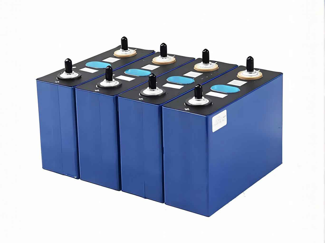
Direct experimental testing of overcharge-induced thermal runaway propagation in a full-scale energy storage cell cluster is prohibitively dangerous and costly. Therefore, computational simulation becomes an indispensable tool for investigating the thermal behavior and propagation characteristics. This study first examines the underlying mechanisms of overcharge thermal runaway. Subsequently, based on experimental data from module-level overcharge tests, a three-dimensional thermal model for an LFP energy storage cell cluster is developed. The model is used to simulate and analyze the propagation dynamics under different overcharge rates, providing critical insights for the safety design and thermal hazard mitigation of energy storage systems.
1. Mechanisms of Overcharge-Induced Thermal Runaway
During normal operation, heat generation within an energy storage cell is relatively low, originating from reversible electrochemical reactions, polarization, and Joule heating. Overcharge dramatically alters this balance. As lithium ions are continuously extracted from the cathode and forced into the anode beyond its capacity, metallic lithium plating occurs. This thickens the Solid Electrolyte Interphase (SEI) layer and increases internal resistance, leading to excessive Joule heating ($Q_j$):
$$Q_j = I^2 R$$
where $I$ is the charging current and $R$ is the internal resistance. The accumulated heat raises the cell temperature, sequentially triggering exothermic chemical decomposition reactions. The primary chain of reactions and their approximate onset temperatures are:
- SEI Decomposition (T > ~90°C): The metastable SEI layer decomposes, releasing heat and exposing the reactive anode material to the electrolyte.
- Anode-Electrolyte Reaction (T > ~120°C): The lithiated anode (e.g., graphite) reacts exothermically with the electrolyte.
- Cathode-Electrolyte Reaction (T > ~170°C for LFP): The delithiated cathode material decomposes, releasing oxygen which can further react with the electrolyte.
- Electrolyte Decomposition (T > ~200°C): The organic solvent in the electrolyte undergoes thermal decomposition.
The total heat generation rate from these side reactions ($Q_s$) is the sum of the individual reaction rates:
$$Q_s(t) = Q_{sei}(t) + Q_{neg}(t) + Q_{pos}(t) + Q_{ele}(t)$$
Each reaction rate follows an Arrhenius-type equation, dependent on the temperature $T$ and the concentration of reactants. For instance, the SEI decomposition reaction rate can be expressed as:
$$R_{sei}(T, C_{sei}) = A_{sei} \cdot (C_{sei})^{m_{sei}} \cdot \exp\left(-\frac{E_{a,sei}}{RT}\right)$$
and the associated heat generation is:
$$Q_{sei} = \Delta H_{sei} \cdot W_c \cdot R_{sei}$$
where $A_{sei}$ is the pre-exponential factor, $E_{a,sei}$ is the activation energy, $R$ is the universal gas constant, $C_{sei}$ is the concentration of unstable lithium, $m_{sei}$ is the reaction order, $\Delta H_{sei}$ is the reaction enthalpy, and $W_c$ is the carbon content per unit volume. Similar formulations apply to the other reactions. The coupling of intense Joule heating and these self-accelerating chemical reactions leads to thermal runaway, where the heat generation rate far exceeds the heat dissipation rate, causing a rapid temperature spike.
2. Heat Transfer and Model Development for Energy Storage Cell Clusters
The propagation of thermal runaway within an energy storage cell cluster is governed by heat transfer. The general energy conservation equation for transient heat conduction is:
$$\rho C_p \frac{\partial T}{\partial t} = \nabla \cdot (k \nabla T) + \dot{Q}$$
where $\rho$ is density, $C_p$ is specific heat capacity, $T$ is temperature, $t$ is time, $k$ is thermal conductivity, and $\dot{Q}$ is the volumetric heat generation rate (from both $Q_j$ and $Q_s$). Heat exchange with the surroundings occurs via convection and radiation:
- Convection: $q_{conv} = h (T_s – T_{\infty})$, where $h$ is the convective heat transfer coefficient.
- Radiation: $q_{rad} = \epsilon \sigma (T_s^4 – T_{surr}^4)$, where $\epsilon$ is emissivity and $\sigma$ is the Stefan-Boltzmann constant.
A three-dimensional thermal model of an LFP energy storage cell cluster was built using COMSOL Multiphysics software. The cluster geometry consists of 14 standard modules (2 wide × 7 high), representing a typical rack configuration. Each module contains 32 prismatic cells (8 series × 4 parallel). The thermal properties of the cell and module casing materials are critical inputs, summarized in Table 1.
| Component | Thermal Conductivity [W/(m·K)] | Density [kg/m³] | Specific Heat [J/(kg·K)] |
|---|---|---|---|
| Module Case (Aluminum) | 238 | 2702 | 903 |
| Cell (Anisotropic) | $k_x$ = 3.72 | 2405 | 1329 |
| $k_y$ = 26 | |||
| $k_z$ = 28 |
The chemical reaction kinetics parameters for the LFP/graphite system, essential for modeling the internal heat source during runaway, are listed in Table 2.
| Reaction | $\Delta H$ (J/g) | $A$ (s⁻¹) | $E_a$ (J/mol) |
|---|---|---|---|
| SEI Decomposition | 257 | 1.667×10¹⁵ | 1.351×10⁵ |
| Anode-Electrolyte | 1714 | 2.5×10¹³ | 1.351×10⁵ |
| Cathode-Electrolyte | 146 | 1.05×10¹¹ | 1.136×10⁵ |
| Electrolyte Decomposition | 155 | 5.1×10²⁵ | 2.74×10⁵ |
The model’s boundary conditions account for natural convection and surface-to-surface radiation between modules and to the ambient environment. The initial condition is room temperature (25°C). The simulation strategy differentiates between two overcharge scenarios based on experimental findings: a 0.4C rate where the module vents gas without flame, and a 0.5C rate leading to fire. For the 0.4C case, the internal heat source $\dot{Q}$ is calculated from the coupled Joule heating and multi-step reaction model. For the 0.5C fire scenario, a simplified but intense heat source is applied to the surfaces of the initiating module based on experimental temperature data to approximate flame impingement and radiation effects, as modeling combustion itself is highly complex. All non-abused modules in the energy storage cell cluster are modeled with a low, constant heat generation rate representing normal standby or float conditions.
3. Simulation Results and Propagation Analysis
The simulation focused on the consequence of a single module (positioned in the middle of the cluster stack) undergoing overcharge. The thermal response of the entire energy storage cell cluster was monitored over time.
3.1 Scenario 1: 0.4C Overcharge (Venting without Fire)
When the initiating module was subjected to a 0.4C overcharge, its temperature increased due to internal reactions. The highest temperature was observed on the bottom surface of the module (~210°C), as it was in direct contact with the heat-generating cells inside. The side and top surfaces reached significantly lower temperatures (below 100°C). The thermal propagation to adjacent modules was limited. The module directly below the abused one showed the most pronounced temperature rise due to conductive heat transfer through the mounting structure, but its peak temperature remained well below the thermal runaway threshold for LFP cells. Modules to the sides and above experienced minimal heating, primarily via radiation and convection through the air gaps. The simulation concluded that under these conditions, the thermal event was largely confined to the initiating energy storage cell module, with no cascading thermal runaway propagation observed in the cluster. The total energy released was insufficient to elevate neighboring cells to their critical trigger temperatures.
3.2 Scenario 2: 0.5C Overcharge (Fire)
The 0.5C overcharge simulation, which incorporated the severe surface heating indicative of a fire, revealed a fundamentally different and hazardous propagation pattern. The initiating module’s top surface temperature exceeded 500°C rapidly. This created an intense localized heat source that primarily radiated and convected heat upwards. The key finding was a vertical upward propagation. The module immediately above the initiating one absorbed this intense heat flux, causing its temperature to rise sharply and triggering its own thermal runaway sequence. This process then repeated: the newly runaway module acted as a powerful heat source for the module above it, leading to a stepwise, upward cascading failure. The temperature profiles of the first four modules in the vertical column clearly show this sequential ignition, as illustrated by the concept below where $T_1$ is the topmost module and $T_4$ is the initiating bottom module:
$$T_4(t) \xrightarrow{\text{Runaway}} \text{High Heat Flux} \rightarrow T_3(t+\Delta t) \xrightarrow{\text{Runaway}} \text{High Heat Flux} \rightarrow T_2(t+2\Delta t) \xrightarrow{\text{Runaway}} …$$
Modules located below or to the sides of the initiation point experienced moderate heating but did not reach runaway conditions within the simulated timeframe, as the dominant heat transfer path was vertically upward. This highlights the critical role of flame-driven heating (high-temperature radiation and convection) in enabling efficient inter-module energy transfer necessary for propagation within the dense energy storage cell cluster.
4. Discussion and Implications for Energy Storage System Safety
The simulation results underscore a significant dependency of propagation risk on the severity of the initial thermal runaway event in the energy storage cell. The 0.4C overcharge, while causing significant damage to the single module, did not present a systemic risk to the cluster under the modeled conditions. In contrast, the 0.5C event leading to open fire created a high-risk scenario for uncontrolled vertical propagation. This has direct implications for the safety design of energy storage containers:
- Thermal Barriers and Inter-modular Insulation: Implementing fire-resistant and thermally insulating materials between vertical stacks of modules can disrupt the primary upward heat transfer path, potentially slowing or halting propagation.
- Detection and Suppression Strategy: Early detection of off-gassing (precursor to fire) is crucial. Fire suppression systems should be designed to target not just the initiator but also to protect the modules directly above it from radiant heating.
- Module Arrangement and Spacing: While spacing is often limited by energy density requirements, designs that minimize direct vertical exposure of one module’s top surface to another’s bottom surface could be beneficial.
- BMS and Electrical Protections: Reinforcing redundant protections against overcharge at the module and string level remains the paramount preventive measure. This includes robust voltage monitoring, accurate SOC algorithms accounting for aging, and reliable charge interruption devices.
The developed model serves as a valuable tool for virtually testing such safety measures and evaluating the robustness of different energy storage cell cluster configurations against thermal runaway propagation.
5. Conclusion
This study employed a three-dimensional thermal model to investigate the propagation characteristics of overcharge-induced thermal runaway within a lithium iron phosphate energy storage cell cluster. The work was grounded in experimental observations differentiating between venting and fire scenarios. The key findings are:
- The overcharge rate and the resultant failure mode (venting vs. fire) of a single module critically determine the propagation risk to the larger energy storage cell cluster.
- A 0.4C overcharge leading to gas venting generated temperatures primarily confined to the initiating module’s structure. Heat transfer to neighboring modules was insufficient to cause cascading thermal runaway under the simulated conditions.
- A 0.5C overcharge leading to a fire created an extreme surface heating condition. The simulation revealed a dominant vertical upward propagation mechanism, where the intense radiant and convective heat flux from the burning module sequentially triggered thermal runaway in the modules stacked directly above it.
- These insights emphasize that fire prevention and containment are essential to preventing large-scale propagation in densely packed energy storage cell clusters. The simulation methodology provides a foundation for designing and evaluating effective thermal management and safety intervention strategies, such as inter-module barriers and targeted suppression, to enhance the resilience of grid-scale energy storage systems.