
In the realm of modern energy storage technologies, the demand for reliable, high-power, and long-lasting systems has grown exponentially, particularly for mobile platforms and harsh environmental conditions. As a researcher involved in advanced power supply projects, I have dedicated efforts to developing a robust cell energy storage system based on lithium-ion batteries. This article details the design, engineering, and real-world application of a high-power cell energy storage system, emphasizing its modular architecture, safety features, and performance under extreme temperatures. The core of this system lies in utilizing high-power lithium iron phosphate (LiFePO4) cells, known for their excellent safety profile and thermal stability, which are critical for vehicular and stationary applications. Throughout this work, the term “cell energy storage system” will be frequently referenced to highlight the integrated nature of battery cells, management electronics, and thermal control in achieving optimal functionality.
The motivation behind this project stems from the need for energy storage solutions that can deliver substantial power outputs while maintaining high reliability over extended periods. Traditional energy storage methods, such as flywheels or capacitors, often fall short in terms of energy density or cost-effectiveness. Lithium-ion batteries, with their high specific energy, low self-discharge, and long cycle life, present an ideal choice. However, challenges like thermal management, cell balancing, and safety under high-stress conditions must be addressed. In this development, we focused on creating a cell energy storage system that not only meets stringent power requirements but also excels in engineering robustness, as verified through rigorous testing and field deployment. The system is designed for a vehicular platform, where space, weight, and environmental adaptability are paramount, making it a quintessential example of advanced cell energy storage system engineering.
The cell energy storage system comprises several key modules: a centralized control unit, multiple high-power energy storage power supplies, each consisting of battery groups and a battery management controller. This modular approach ensures ease of maintenance and scalability. For instance, each energy storage power supply includes two battery groups (Group A and Group B) connected in series, along with a battery management controller that oversees charging, discharging, and safety protocols. The battery groups are built using LiFePO4 cells configured in a series-parallel arrangement to achieve the desired voltage and capacity. To provide a clear overview, Table 1 summarizes the primary technical specifications of the cell energy storage system, highlighting its power capabilities and operational range.
| Parameter | Value | Unit |
|---|---|---|
| Nominal Capacity | 16 | A·h |
| Voltage Range | 210–330 | V |
| Maximum Output Power | 40 | kW |
| Discharge Time | 200 | s |
| Stored Energy | 4.3 | kW·h |
| Operating Temperature | −20 to 60 | °C |
| Cycle Life (at 55% DOD) | >1000 | cycles |
The heart of this cell energy storage system is the lithium iron phosphate cell, chosen for its inherent safety and high-power performance. These cells exhibit a stable voltage plateau and minimal risk of thermal runaway, even under abusive conditions. The selected cell model, with a capacity of 8 A·h, demonstrates impressive discharge characteristics, as shown by its capability to deliver high currents up to 30 C rates while maintaining capacity retention. The discharge behavior can be modeled using a simplified equation that relates voltage to state-of-charge (SOC) and current:
$$V_{cell}(t) = V_{oc}(SOC) – I(t) \cdot R_{int}(SOC, T)$$
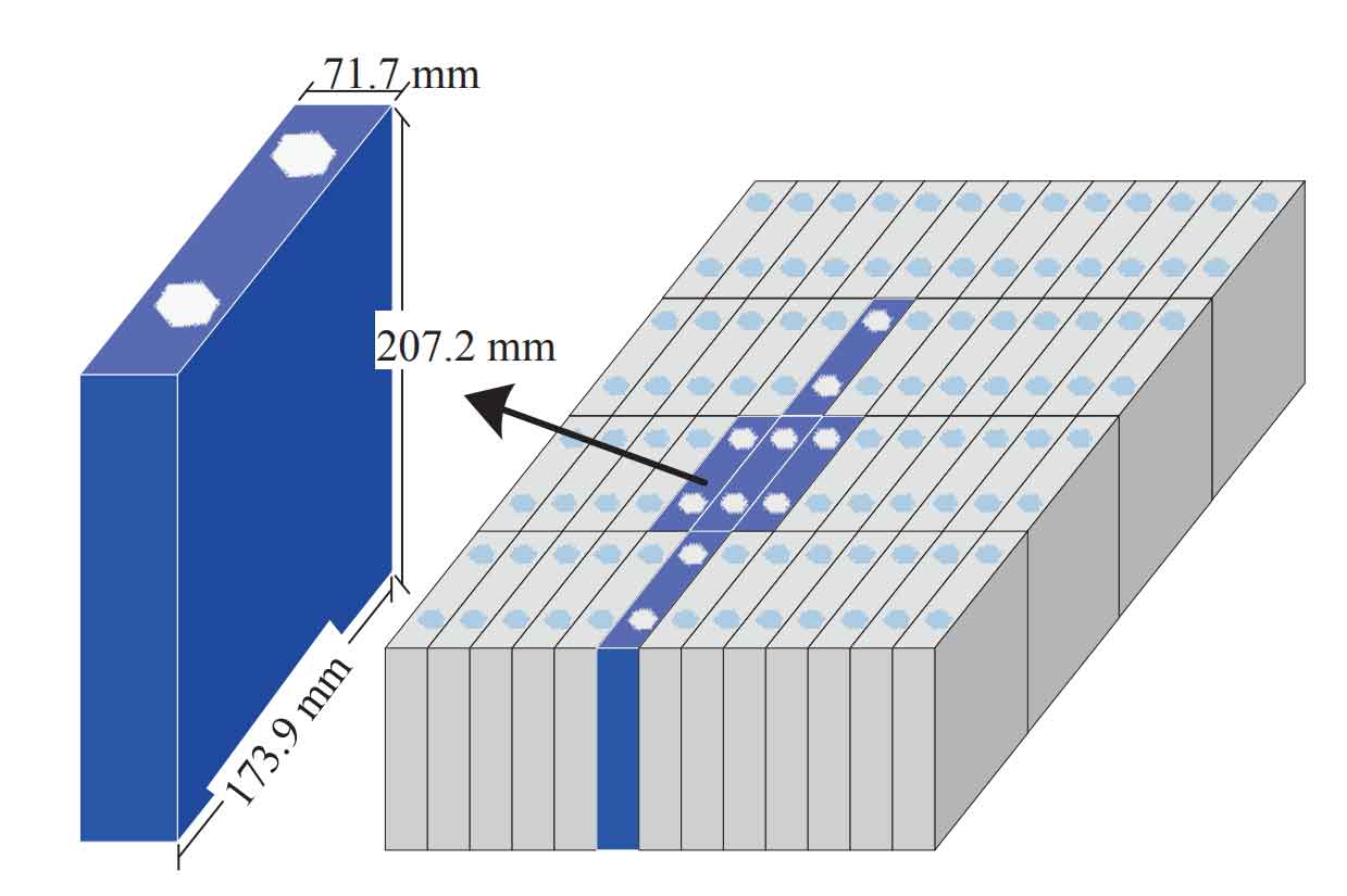
where \( V_{cell}(t) \) is the cell voltage at time \( t \), \( V_{oc}(SOC) \) is the open-circuit voltage as a function of SOC, \( I(t) \) is the discharge current, and \( R_{int}(SOC, T) \) is the internal resistance dependent on SOC and temperature \( T \). This equation underscores the importance of managing SOC and temperature to maintain efficiency in a cell energy storage system. To visualize the physical form of these cells and their assembly into modules, the following image provides insight into the single-cell and group configurations, which are critical for understanding the scalability of the system.
Thermal management is a pivotal aspect of any high-power cell energy storage system, as excessive heat can degrade battery life and pose safety hazards. In our design, we employed liquid cooling with a dedicated circuit to maintain optimal operating temperatures. The thermal dynamics were analyzed through simulation, using the heat conduction equation to predict temperature distribution within the battery pack:
$$\rho c_p \frac{\partial T}{\partial t} = \nabla \cdot (k \nabla T) + q_{gen}$$
where \( \rho \) is density, \( c_p \) is specific heat capacity, \( k \) is thermal conductivity, \( T \) is temperature, and \( q_{gen} \) is the heat generation rate per unit volume from battery reactions. For LiFePO4 cells, \( q_{gen} \) can be approximated as \( I^2 R_{int} + I \left( \frac{\partial V_{oc}}{\partial T} \right) \), accounting for Joule heating and entropic effects. Simulation results indicated that under the most severe operational scenario—starting at 60% SOC in a 60°C environment, followed by cooling, charging, and discharging cycles—the maximum cell temperature reached 45°C, well below the 50°C safety limit. This ensures the longevity and reliability of the cell energy storage system, as detailed in Table 2, which compares simulated and measured thermal metrics.
| Metric | Simulated Value | Measured Value | Unit |
|---|---|---|---|
| Peak Temperature (First Discharge) | 44.1 | 45 | °C |
| Peak Temperature (Second Charge) | 39.5 | 40 | °C |
| Steady-State Temperature Range | 31–35 | 30–35 | °C |
| Coolant Flow Rate | 5 | 5 | L/min |
Battery management is crucial for the health and efficiency of a cell energy storage system. Our system incorporates high-performance sampling and active balancing modules, along with a centralized battery management system (BMS). The BMS continuously monitors individual cell voltages, temperatures, and overall pack status, using algorithms to initiate balancing when voltage disparities exceed 50 mV. The balancing process, based on a switched-capacitor or inductor-based topology, can be described by the charge transfer equation:
$$Q_{bal} = C_{eq} \cdot \Delta V$$
where \( Q_{bal} \) is the charge transferred during balancing, \( C_{eq} \) is the equivalent capacitance of the balancing circuit, and \( \Delta V \) is the voltage difference between cells. This active approach minimizes energy loss and extends cycle life, which is essential for a cell energy storage system subjected to frequent charge-discharge cycles. Additionally, the BMS calculates state-of-charge (SOC) and state-of-health (SOH) using coulomb counting and model-based estimators, such as:
$$SOC(t) = SOC_0 – \frac{1}{C_{nom}} \int_0^t I(\tau) \, d\tau$$
where \( SOC_0 \) is the initial SOC, \( C_{nom} \) is the nominal capacity, and \( I(\tau) \) is the current. For improved accuracy, we also incorporated a Kalman filter to account for measurement noise and model uncertainties, ensuring reliable operation of the cell energy storage system.
Engineering validation is a cornerstone of developing a robust cell energy storage system. We conducted extensive tests covering transportation safety, environmental adaptability, reliability, maintainability, and electromagnetic compatibility. Transportation safety tests adhered to international standards, such as the UN Manual of Tests and Criteria, involving vibration, shock, and thermal cycling to simulate logistics stresses. The vibration test, for example, applied sinusoidal sweeps from 7 Hz to 200 Hz in three orthogonal axes, with each axis subjected to 3 hours of exposure. These tests confirmed that the cell energy storage system can withstand harsh handling without compromising integrity.
Reliability analysis was performed using established military standards (e.g., GJB/Z 299C) to estimate mean time between failures (MTBF). The overall cell energy storage system, comprising multiple modules, achieved an MTBF of approximately 5400 hours, as derived from component-level failure rates. Table 3 breaks down the reliability metrics for key subsystems, illustrating the contributions of each to the system’s overall dependability. This quantitative assessment underscores the durability of our cell energy storage system in demanding applications.
| Subsystem | Failure Rate (per hour) | Quantity | Contribution to System Failure Rate | MTBF (hours) |
|---|---|---|---|---|
| Centralized Controller | 1.42 × 10⁻⁵ | 1 | 1.42 × 10⁻⁵ | 70,400 |
| Battery Management Controller | 7.86 × 10⁻⁶ | 7 | 5.50 × 10⁻⁵ | 127,200 |
| Battery Group A | 8.37 × 10⁻⁶ | 7 | 5.86 × 10⁻⁵ | 119,500 |
| Battery Group B | 8.37 × 10⁻⁶ | 7 | 5.86 × 10⁻⁵ | 119,500 |
| Total System | 1.84 × 10⁻⁴ | 5,400 | ||
Maintainability and testability were also prioritized in the cell energy storage system design. The modular architecture allows for rapid replacement of faulty units, with an average repair time (MTTR) of less than 30 minutes at the field level. Each module, including battery groups and controllers, is designed to weigh under 60 kg, facilitating manual handling. The BMS provides comprehensive diagnostic data, achieving a fault detection rate of 100% and isolation to within three replaceable units, with zero false alarms. This enhances the operational readiness of the cell energy storage system, reducing downtime in critical scenarios.
Environmental adaptability tests verified the cell energy storage system’s performance across temperature extremes, from −20°C to 60°C, and under high humidity conditions. Electromagnetic compatibility (EMC) was ensured through shielded cabling, power factor correction in chargers, and compliance with standards like EN55022 and GB/T18487.3. The charger, integrated into the system, features a power factor of 0.99 and harmonic currents below 3%, minimizing interference with other vehicular electronics. These attributes make the cell energy storage system suitable for integration into complex mobile platforms where EMC is critical.
The ultimate validation of this cell energy storage system came from field deployment in high-temperature regions, where ambient temperatures exceeded 55°C. A batch of 21 energy storage power supplies was deployed and operated continuously for over 12 months, powering mobile equipment without any failures. This real-world application demonstrated the system’s robustness under sustained thermal stress, confirming the efficacy of the thermal management and battery balancing strategies. Data loggers recorded key parameters, such as cell voltages and temperatures, which remained within safe limits throughout the period. This success highlights the practical viability of our cell energy storage system for harsh environments, paving the way for broader adoption in similar settings.
In conclusion, the development and application of this high-power cell energy storage system represent a significant advancement in energy storage technology. By leveraging lithium iron phosphate cells, advanced thermal design, and intelligent battery management, we have created a system that delivers reliable power in challenging conditions. The engineering rigor applied—from simulation and testing to field validation—ensures that the cell energy storage system meets stringent requirements for safety, longevity, and performance. As energy storage needs continue to evolve, particularly for electric vehicles and renewable integration, the insights gained from this project will inform future innovations. The cell energy storage system, as described herein, serves as a benchmark for integrating high-power batteries into demanding applications, underscoring the importance of holistic design in achieving operational excellence.
Throughout this article, the term “cell energy storage system” has been emphasized to reflect the interconnected nature of its components. From cell selection to system-level integration, every aspect was optimized to create a cohesive unit capable of delivering 40 kW of power with high efficiency. The formulas and tables provided offer a quantitative foundation for understanding its capabilities, while the field results attest to its real-world reliability. Moving forward, further enhancements could include higher energy density cells, advanced cooling techniques, and machine learning-based BMS algorithms to push the boundaries of what a cell energy storage system can achieve. This work not only addresses immediate technological needs but also contributes to the broader landscape of sustainable energy solutions, where robust and scalable storage systems are paramount.