
In modern power systems, the integration of renewable energy sources, particularly wind power, has become increasingly prevalent. Among wind turbine technologies, doubly-fed induction generators (DFIGs) are widely adopted due to their advantages such as low output harmonic content, high wind energy utilization, and reduced converter capacity. However, high penetration of DFIG-based wind farms poses significant challenges to grid frequency stability. This is primarily because DFIGs operate through power electronic interfaces that decouple rotor speed from grid frequency, and they often operate at maximum power point tracking, leaving limited active power reserve for primary frequency regulation. As wind power penetration grows, the burden on conventional generators for frequency control intensifies, necessitating innovative strategies to enhance grid frequency response.
Energy storage batteries have emerged as a promising solution for ancillary services, including frequency regulation, due to their fast response, high energy density, and flexible control capabilities. When integrated with wind farms, energy storage batteries can provide immediate active power support to mitigate frequency deviations. However, relying solely on energy storage battery for frequency control may lead to insufficient inertia response and large frequency deviations, especially under high disturbance scenarios. To address this, the virtual synchronous generator (VSG) control strategy applied to grid-side converters (GSCs) can emulate the inertial and primary frequency regulation characteristics of synchronous generators, thereby improving the overall frequency performance. In this context, we propose a comprehensive control strategy that leverages both energy storage battery and VSG capabilities, considering dynamic frequency inertia characteristics for enhanced grid primary frequency control.
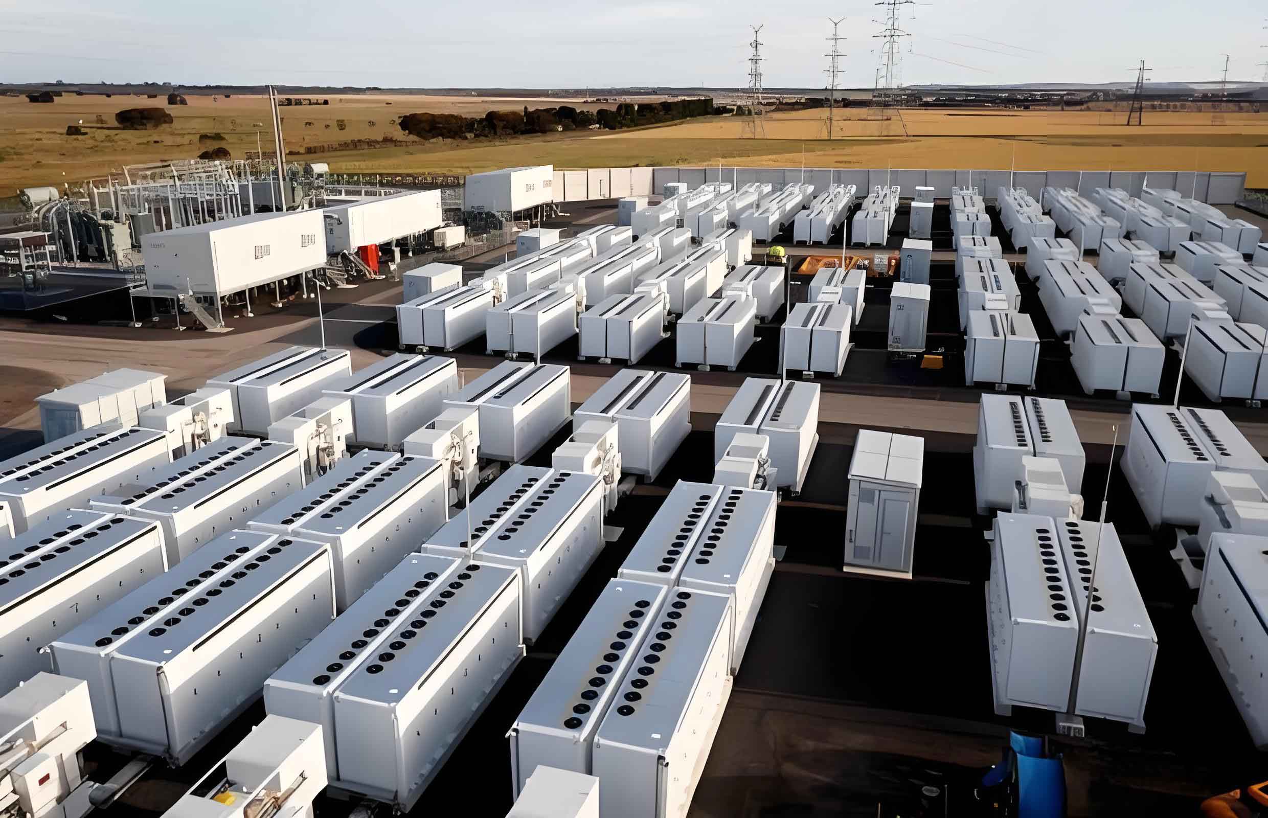
The core idea of our approach is to synergistically combine the fast response of energy storage battery with the virtual inertia and damping properties of VSG control. We design an additional active power module that incorporates both virtual inertia and droop control from the energy storage battery. The virtual inertia control provides transient power support to enhance inertia response, while the droop control offers steady-state power adjustment for primary frequency regulation. These powers are then used as additional inputs for variable rotor inertia control and output feedback model predictive control within the VSG framework. Specifically, the variable rotor inertia control adapts the virtual inertia based on system frequency deviation and rate of change, enabling real-time adjustment to system dynamics. Meanwhile, the output feedback model predictive control establishes a feedback channel between rotor angular frequency increment and torque increment, allowing dynamic prediction and compensation of frequency deviations. This integrated strategy aims to reduce both maximum frequency deviation and rate of change of frequency (RoCoF), thereby improving grid stability.
To elaborate, the energy storage battery participates in grid frequency control through two main mechanisms: virtual inertia control and droop control. The virtual inertia control responds to the rate of change of frequency, providing rapid power injection or absorption to mimic the inertia response of traditional synchronous generators. The droop control, on the other hand, adjusts power output proportionally to frequency deviations, similar to the governor action in synchronous machines. The combined output from these controls is integrated into the VSG control loop to augment its frequency regulation capabilities. This integration is crucial because the energy storage battery can quickly compensate for power imbalances, while the VSG provides sustained support through its virtual rotor dynamics.
The additional active power from the energy storage battery is defined as follows. For droop control, the power is given by:
$$
\Delta P_{dro\_1} = K_1 (f_{ref} – f)
$$
where \(K_1\) is the droop coefficient of the energy storage battery, \(f_{ref}\) is the nominal grid frequency, and \(f\) is the measured system frequency. For virtual inertia control, the power is:
$$
\Delta P_{ine\_2} = K_2 \frac{d(f_{ref} – f)}{dt}
$$
where \(K_2\) is the virtual inertia coefficient of the energy storage battery. These powers are utilized in the VSG control to enhance frequency response. Specifically, \(\Delta P_{dro\_1}\) is added to the reference power for output feedback model predictive control, and \(\Delta P_{ine\_2}\) is added to the reference power for variable rotor inertia control.
The VSG control is based on emulating the swing equation of a synchronous generator. The mechanical motion equation of a virtual synchronous generator is:
$$
J \frac{d\omega}{dt} = T_m – T_e – T_d = T_m – T_e – D(\omega – \omega_{ref})
$$
where \(J\) is the rotor inertia, \(\omega\) is the rotor angular velocity (\(\omega = 2\pi f\)), \(T_m\) is the mechanical torque, \(T_e\) is the electromagnetic torque, \(T_d\) is the damping torque, \(D\) is the damping coefficient, and \(\omega_{ref}\) is the nominal angular velocity. The virtual rotor angle \(\delta\) is obtained by integrating the angular velocity deviation:
$$
\delta = \int (\omega – \omega_{ref}) dt
$$
In conventional VSG control, \(J\) and \(D\) are fixed parameters. However, to better match grid requirements, we propose a variable rotor inertia control strategy where \(J\) is adjusted dynamically based on system conditions.
The variable rotor inertia control aims to optimize the inertia response by varying \(J\) according to the product of rotor angular velocity deviation and its rate of change. The adjusted inertia \(J_1\) is defined as:
$$
J_1 =
\begin{cases}
J_0 + k \left| \frac{d\omega}{dt} \right|, & \text{if } \frac{d\omega}{dt} (\omega – \omega_{ref}) > 0 \\
J_0 – k \left| \frac{d\omega}{dt} \right|, & \text{if } \frac{d\omega}{dt} (\omega – \omega_{ref}) < 0
\end{cases}
$$
where \(J_0\) is the steady-state inertia constant, and \(k\) is a positive constant. This formulation ensures that during frequency disturbances, the inertia is increased to suppress frequency changes when the frequency deviation and its rate of change have the same sign (e.g., frequency falling and RoCoF negative), and decreased to accelerate recovery when they have opposite signs. This adaptive inertia enhances the system’s ability to limit frequency nadir and reduce settling time.
Furthermore, we introduce an output feedback model predictive control (OFMPC) strategy for the VSG to improve primary frequency regulation. The incremental form of the rotor motion equation and droop control is:
$$
\frac{d\Delta\omega}{dt} = -\frac{D}{J} \Delta\omega + \frac{1}{J} \Delta T_m – \frac{1}{J} \Delta T_e
$$
$$
\Delta T = m \Delta\omega
$$
where \(\Delta\omega\) is the rotor angular frequency increment, \(\Delta T_m\) is the mechanical torque increment, \(\Delta T_e\) is the disturbance torque increment, \(\Delta T\) is the output feedback torque increment (\(\Delta T = \Delta P / \omega_{ref}\)), and \(m\) is the torque droop coefficient. Discretizing this system yields:
$$
x(k+1) = A x(k) + B u(k) + D^- d(k)
$$
$$
y(k) = C x(k)
$$
with \(x(k) = \Delta\omega(k)\), \(u(k) = \Delta T_m(k)\), \(d(k) = \Delta T_e(k)\), \(y(k) = \Delta T(k)\), \(A = -D/J\), \(B = 1/J\), \(D^- = -1/J\), and \(C = m\). The predictive model over a horizon \(N\) with control horizon \(M\) (\(N \geq M\)) is constructed, and the cost function to minimize is:
$$
\min_{\Delta U} C = (Y_{ref} – Y)^T Q (Y_{ref} – Y) + \Delta U^T R \Delta U
$$
where \(Y_{ref}\) is the reference torque vector, \(Y\) is the predicted output vector, \(Q\) and \(R\) are weight matrices, and \(\Delta U\) is the control increment vector. Solving this optimization yields the optimal control sequence, with the first element applied in a receding horizon fashion. The feedback compensation law is derived as:
$$
\Delta u(k) = |Z| \Delta T(k) – Z F \Delta\omega(k) – Z \Phi_D \Delta T_e(k)
$$
where \(Z = (\Phi_B^T Q \Phi_B + R)^{-1} \Phi_B^T Q\), and \(F\), \(\Phi_B\), \(\Phi_D\) are matrices from the prediction model. This OFMPC strategy dynamically adjusts torque based on predicted frequency deviations, effectively reducing steady-state error and overshoot.
The overall control strategy execution involves coordinating the energy storage battery and VSG controls. The energy storage battery provides additional power via virtual inertia and droop controls, which are integrated into the VSG’s variable rotor inertia and OFMPC modules, respectively. The control loops operate simultaneously, with the variable rotor inertia control focusing on inertia support and the OFMPC on primary regulation. This synergy ensures robust frequency response under various disturbances.
To validate the proposed strategy, we conduct simulations using a regional power system model in MATLAB/Simulink. The system includes synchronous generators, a DFIG-based wind farm, and an energy storage battery. The wind farm comprises 35 DFIG units of 1.5 MW each, and the energy storage battery has a capacity of 2.63 MW with state-of-charge limits between 0.1 and 0.9. The system parameters are summarized in the following tables.
| Generator | d-axis syn. reactance (p.u.) | d-axis trans. reactance (p.u.) | d-axis subtrans. reactance (p.u.) | q-axis syn. reactance (p.u.) | q-axis trans. reactance (p.u.) | q-axis subtrans. reactance (p.u.) | Leakage reactance (p.u.) |
|---|---|---|---|---|---|---|---|
| G1 | 0.896 | 0.120 | 0.089 | 0.865 | 0.864 | 0.089 | 0.052 |
| G2 | 0.146 | 0.061 | 0.040 | 0.097 | 0.097 | 0.060 | 0.034 |
| Parameter | Value | Parameter | Value | Parameter | Value |
|---|---|---|---|---|---|
| Rated voltage (V) | 575 | Rotor resistance (p.u.) | 0.005 | Inertia constant (s) | 5.04 |
| Rated frequency (Hz) | 50 | Rotor inductance (p.u.) | 0.156 | DC bus capacitance (F) | 0.35 |
| Stator resistance (p.u.) | 0.00706 | Magnetizing inductance (p.u.) | 2.9 | Grid-side filter inductance (p.u.) | 0.15 |
| Stator inductance (p.u.) | 0.171 | Number of pole pairs | 3 | Grid-side filter resistance (p.u.) | 0.0015 |
The control parameters are set as follows: for the energy storage battery, \(K_1 = 30\) and \(K_2 = 0.3\); for variable rotor inertia control, \(D = 10\), \(J_0 = 0.2 \, \text{kg} \cdot \text{m}^2\), and \(k = 50\); for OFMPC, \(m = -0.0018 \, \text{N} \cdot \text{s} / \text{Hz}\), \(J = 1.8 \, \text{kg} \cdot \text{m}^2\), and \(Q\) and \(R\) are identity matrices. We compare our strategy with three existing approaches: (1) no frequency control from wind turbines (WT no control), (2) combined inertia control (virtual inertia and droop) for wind turbines (combined inertia control), and (3) energy storage battery participation in frequency control without VSG enhancement (energy storage only). The performance metrics include maximum frequency deviation (\(\Delta f_{max}\)), steady-state frequency deviation (\(\Delta f_{ste}\)), maximum wind power output (\(\Delta P_{ge,max}\)), initial frequency decline rate (\(d_{ini}\)), maximum frequency peak-to-valley difference (\(\Delta f_{pv,max}\)), and maximum wind power peak-to-valley difference (\(\Delta P_{pv,max}\)).
We simulate three disturbance scenarios: step load increase, step wind speed increase, and random load variations. For the step load scenario, a 30 MW load is added at 40 s. The frequency deviations and wind power outputs are analyzed, and key metrics are summarized in Table 3.
| Control Strategy | \(\Delta f_{max}\) (Hz) | \(\Delta f_{ste}\) (Hz) | \(\Delta P_{ge,max}\) (p.u.) | \(d_{ini}\) (Hz/s) |
|---|---|---|---|---|
| WT no control | 0.375 | 0.075 | 0.269 | 6.314 |
| Combined inertia control | 0.288 | 0.075 | 0.373 | 5.145 |
| Energy storage only | 0.224 | 0.063 | 0.382 | 4.011 |
| Proposed strategy | 0.208 | 0.058 | 0.398 | 3.078 |
The results show that our proposed strategy reduces \(\Delta f_{max}\) by 7.14% compared to energy storage only, and by 27.78% compared to combined inertia control. The steady-state deviation is also lower, and the wind power output is higher, indicating better frequency regulation and energy utilization. The initial frequency decline rate is significantly reduced, demonstrating enhanced inertia response.
For the step wind speed scenario, a 0.02 p.u. step increase is applied at 50 s. The frequency deviations are positive due to increased wind power injection. The metrics are given in Table 4.
| Control Strategy | \(\Delta f_{max}\) (Hz) | \(\Delta f_{ste}\) (Hz) | \(\Delta P_{ge,max}\) (p.u.) |
|---|---|---|---|
| WT no control | 0.0204 | 0.0150 | 0.519 |
| Combined inertia control | 0.0191 | 0.0150 | 0.519 |
| Energy storage only | 0.0178 | 0.0138 | 0.539 |
| Proposed strategy | 0.0176 | 0.0133 | 0.544 |
Our strategy achieves the lowest frequency deviations and highest wind power output, confirming its effectiveness in mitigating over-frequency events. The energy storage battery provides rapid power absorption, while the VSG control stabilizes the system.
In the random load disturbance scenario, a 40 s random load variation with fluctuations up to 10 MW is applied. The performance metrics are summarized in Table 5.
| Control Strategy | \(\Delta f_{pv,max}\) (Hz) | \(\Delta f_{max}\) (Hz) | \(\Delta P_{pv,max}\) (p.u.) | \(\Delta P_{ge,max}\) (p.u.) |
|---|---|---|---|---|
| WT no control | 0.0071 | 0.0036 | 0.0044 | 0.2702 |
| Combined inertia control | 0.0061 | 0.0034 | 0.0061 | 0.2703 |
| Energy storage only | 0.0021 | 0.0011 | 0.0108 | 0.2728 |
| Proposed strategy | 0.0011 | 0.0006 | 0.0122 | 0.2736 |
Our strategy outperforms others in all metrics, with the smallest frequency deviations and highest wind power output. This highlights the robustness of the integrated control under variable conditions. The energy storage battery, coupled with VSG adaptive control, effectively smoothens frequency fluctuations and maintains grid stability.
The superiority of our approach can be attributed to several factors. First, the energy storage battery provides fast and precise power compensation, addressing immediate power imbalances. Second, the variable rotor inertia control dynamically adjusts virtual inertia to match system dynamics, improving transient response. Third, the output feedback model predictive control optimizes power output based on predictions, reducing steady-state errors. The synergy between these components ensures comprehensive frequency support.
To further analyze the control mechanisms, we derive the frequency response model of the system. The overall system frequency dynamics can be approximated by:
$$
\Delta f(s) = \frac{1}{2H s + D} \left( \Delta P_m(s) – \Delta P_e(s) + \Delta P_{bat}(s) \right)
$$
where \(H\) is the equivalent inertia constant, \(D\) is the damping coefficient, \(\Delta P_m\) is the mechanical power change from generators, \(\Delta P_e\) is the load disturbance, and \(\Delta P_{bat}\) is the power from the energy storage battery. With our control strategy, \(\Delta P_{bat}\) includes contributions from both virtual inertia and droop controls, enhanced by VSG adjustments. The closed-loop transfer function can be derived to show improved stability margins.
For instance, the effect of variable rotor inertia control on frequency nadir can be quantified. The frequency nadir \(\Delta f_{min}\) after a step load disturbance \(\Delta P_L\) is approximated by:
$$
\Delta f_{min} \approx -\frac{\Delta P_L}{D} \left( 1 – e^{-\frac{D}{2H} t_{min}} \right)
$$
where \(t_{min}\) is the time to reach nadir. By increasing \(H\) adaptively during the initial drop, our strategy reduces \(\Delta f_{min}\), as observed in simulations.
Additionally, the energy storage battery’s state-of-charge (SOC) management is crucial for sustained operation. We incorporate SOC constraints to prevent overcharge or deep discharge. The SOC dynamics are given by:
$$
SOC(t) = SOC_0 – \frac{1}{E_{bat}} \int_0^t P_{bat}(\tau) d\tau
$$
where \(SOC_0\) is the initial SOC, \(E_{bat}\) is the energy capacity, and \(P_{bat}\) is the power output (positive for discharge). In our control, we limit \(P_{bat}\) within safe SOC bounds, ensuring long-term viability. This is integrated into the energy storage battery control logic, but detailed SOC management is beyond the scope of this paper.
The proposed strategy also considers scalability for larger systems. For multiple energy storage batteries and VSGs, coordination can be achieved through distributed control schemes. The power sharing among units can be based on frequency deviations or consensus algorithms. However, in this study, we focus on a single energy storage battery and VSG pair to demonstrate core principles.
In conclusion, we have presented a novel control strategy for energy storage battery participation in grid primary frequency control, considering dynamic frequency inertia characteristics. The strategy combines the fast response of energy storage battery with the virtual inertia and damping of VSG control, using variable rotor inertia and output feedback model predictive techniques. Simulation results under various disturbances confirm that our approach significantly reduces maximum frequency deviation, steady-state error, and rate of change of frequency, while maintaining high wind power output. The energy storage battery plays a pivotal role in providing immediate power support, and the VSG enhancement ensures robust and adaptive frequency regulation. Future work will explore real-time implementation, coordination of multiple energy storage batteries, and integration with other renewable sources. This research contributes to improving grid stability in high-renewable penetration scenarios, highlighting the importance of energy storage battery in modern power systems.