
The global energy landscape is undergoing a profound transformation, driven by the urgent need for sustainability and energy security. Distributed Generation (DG) systems, particularly those harnessing solar photovoltaic (PV) and wind energy, have seen exponential growth and integration into modern power grids. At the heart of this integration lies a critical power electronic interface: the utility interactive inverter. This device is responsible for converting the direct current (DC) output from renewable sources into high-quality alternating current (AC) that is synchronized with the utility grid. The performance and stability of these inverters are paramount, as they directly impact power quality, grid reliability, and the safe operation of the entire network.
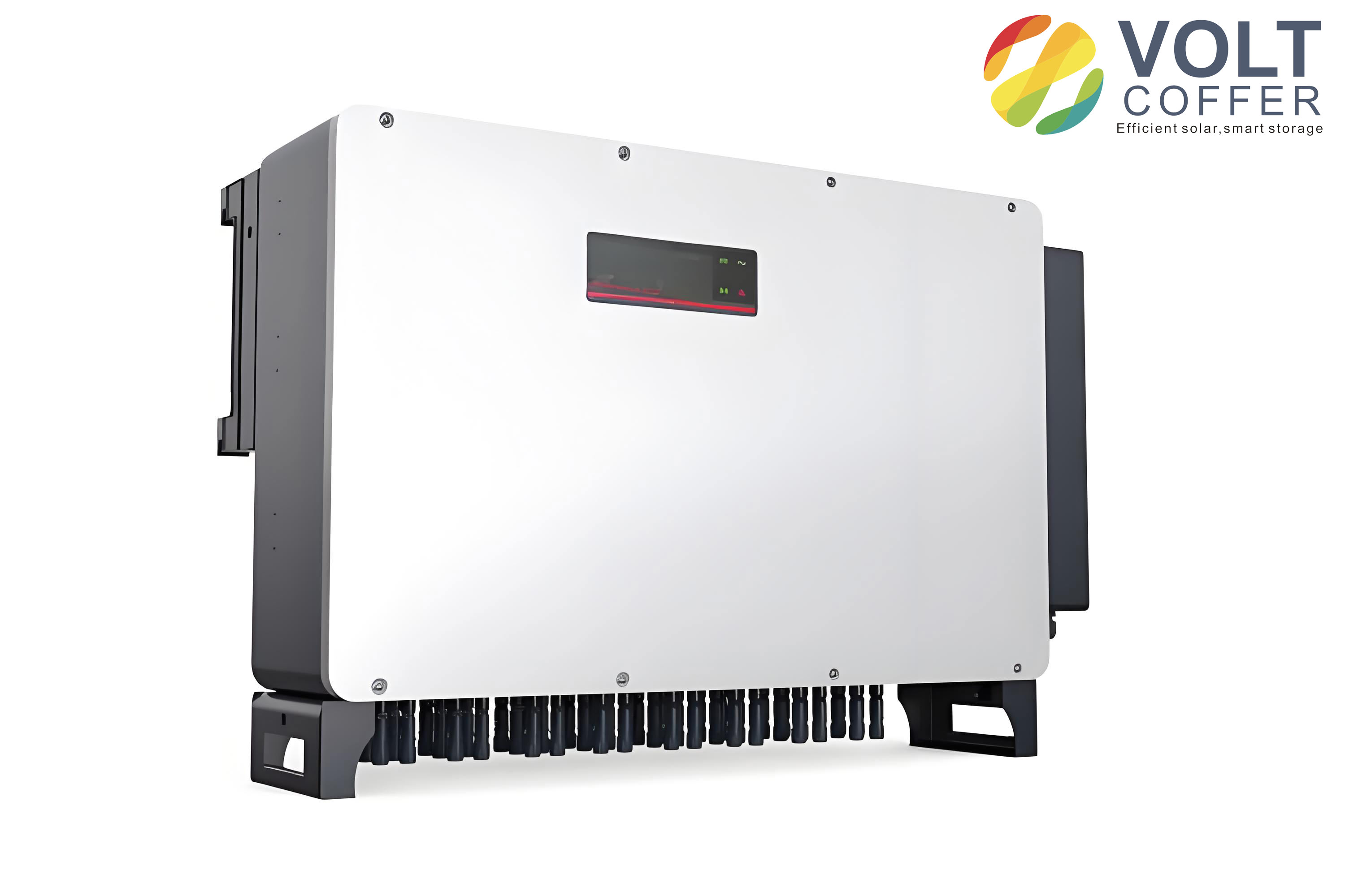
The output stage of a utility interactive inverter typically requires a filter to attenuate high-frequency switching harmonics generated by the pulse-width modulation (PWM) process. While simple L-filters are an option, the LCL filter topology has become the de facto standard for higher-power applications due to its superior harmonic attenuation capability with smaller inductor sizes. An LCL filter consists of an inverter-side inductor (\(L_1\)), a filter capacitor (\(C\)), and a grid-side inductor (\(L_2\)). However, this third-order network introduces a resonant peak that can lead to instability if not properly damped. Traditional passive damping, using resistors in series with the capacitor, is simple but incurs significant power losses. Consequently, active damping methods, which use control algorithms to emulate damping resistors, are preferred for their high efficiency.
Among various current control strategies for LCL-type utility interactive inverters, the Weighted Average Current (WAC) control has attracted considerable attention. Its primary appeal lies in its potential to achieve loop shaping that reduces the system’s apparent order, simplifying controller design and stability analysis. The core idea is to feed back a weighted sum of the inverter-side current (\(i_{L1}\)) and the grid-side current (\(i_g\)):
$$
i_{wac} = (1-\beta) i_{L1} + \beta i_g
$$
where \(\beta\) is the weighting coefficient. By carefully selecting \(\beta\) and a proportional feedforward term from the point of common coupling (PCC) voltage (\(U_{pcc}\)), the open-loop transfer function from the reference current to the weighted current can be reduced from a third-order to a first-order system under ideal, continuous-time conditions. However, this elegant property faces significant challenges in practical digital implementations. The non-negligible computational and PWM delays inherent in digital control, often modeled as a pure delay \(G_d(s) \approx e^{-1.5sT_s}\) (where \(T_s\) is the sampling period), can distort this characteristic. Furthermore, the presence of grid impedance (\(L_g\)), which is highly variable and can be substantial in weak grids (characterized by a low Short-Circuit Ratio, SCR), further destabilizes the system. Crucially, even when the weighted current loop is stabilized, the actual grid current (\(i_g\)), which is the ultimate control objective, may still contain a “hidden” resonance inherited from the LCL filter’s physical structure, leading to harmonic instability and poor power quality.
This article addresses these critical shortcomings of the traditional WAC strategy for LCL utility interactive inverters. We propose an improved WAC control method that ensures robust stability and high grid current quality even under severe grid impedance variations and digital delay effects. The proposed strategy introduces two key modifications: First, a capacitive current feedback loop is integrated to provide active damping, explicitly suppressing the resonance in the grid current. Second, new degrees of freedom are introduced into the feedback and feedforward paths via additional weighting coefficients. This allows for a deliberate reconfiguration of the system’s zeros and poles, effectively counteracting the detrimental effects of digital delay and grid impedance, thereby recovering and maintaining the desirable reduced-order characteristic of the open-loop system. A comprehensive stability analysis based on passivity theory is conducted to guide the parameter design, ensuring the inverter’s output impedance remains passive within the Nyquist frequency range for robust stability in weak-grid conditions. The effectiveness of the proposed method is validated through detailed simulations and experimental results on a single-phase utility interactive inverter prototype.
1. Fundamental Analysis of Traditional WAC Control and Its Limitations
To establish a foundation, we first analyze the structure and inherent limitations of the traditional WAC control scheme for an LCL-type utility interactive inverter. The system diagram is shown below.
The primary control objective is to force the grid current \(i_g\) to track its sinusoidal reference \(i_{ref}\). The WAC controller uses a Proportional-Resonant (PR) or other suitable compensator \(G_R(s)\) to regulate the error between \(i_{ref}\) and the measured weighted current \(i_{wac}\). The output of the compensator, along with a feedforward term \(G_f(s)U_{pcc}\), generates the modulation signal for the PWM block, represented by its gain \(K_{PWM} = U_{dc}/U_{tri}\). The LCL filter dynamics and the grid impedance \(L_g\) complete the plant model. The digital control delay \(G_d(s)\) is a critical element in the loop.
The open-loop transfer function \(T_{i_{ref}-i_{wac}}(s)\) and the closed-loop transfer function \(T_{i_{ref}-i_g}(s)\) from the reference to the grid current are derived from the block diagram. In the ideal, delay-free continuous-time case (\(G_d(s)=1\)), by setting the weighting factor \(\beta\) and the feedforward gain \(G_f\) as:
$$
\beta = \frac{L_1}{L_1 + L_2}, \quad G_f = \frac{1}{K_{PWM}}
$$
the third-order terms in the open-loop transfer function cancel out, leading to a simplified first-order system:
$$
T_{i_{ref}-i_{wac}}^{ideal}(s) = \frac{G_R(s) K_{PWM}}{s(L_1 + L_2)}
$$
This is the celebrated “order reduction” property. However, this property is fragile. When the inevitable digital control delay is included, the cancellation is imperfect. The delay can be approximated using a second-order Padé approximation for analysis:
$$
G_d(s) \approx \frac{1 – 0.75sT_s + 0.083 (1.5sT_s)^2}{1 + 0.75sT_s + 0.083 (1.5sT_s)^2}
$$
More critically, the stability of the weighted current loop does not guarantee the stability of the actual grid current. Analyzing the denominator of the closed-loop transfer function \(T_{i_{ref}-i_g}(s)\) reveals that, even with the ideal parameter setting from the equation for \(\beta\) and \(G_f\), the characteristic equation retains the resonant mode of the LCL filter:
$$
\omega_r = \sqrt{\frac{L_1 + L_2}{L_1 L_2 C}}
$$
This is the “hidden resonance” problem. The weighted current is a virtual, stabilized signal, but the physical grid current can still oscillate at \(\omega_r\) if excited by disturbances or grid harmonics.
The destabilizing effect of grid impedance is profound. As the grid weakens (i.e., \(L_g\) increases), the effective grid-side inductance becomes \(L_{T} = L_2 + L_g\). This shift alters the system’s open-loop frequency response. The following table summarizes a typical parameter set for a single-phase utility interactive inverter used in our analysis.
| Parameter | Symbol | Value |
|---|---|---|
| Grid Voltage (RMS) | \(U_g\) | 220 V |
| DC Link Voltage | \(U_{dc}\) | 360 V |
| Switching Frequency | \(f_{sw}\) | 10 kHz |
| Sampling Frequency | \(f_s\) | 20 kHz |
| Inverter-side Inductor | \(L_1\) | 0.6 mH |
| Grid-side Inductor | \(L_2\) | 0.4 mH |
| Filter Capacitor | \(C\) | 5 μF |
| Passive Damping Resistor | \(R_d\) | 1.1 Ω |
A Bode plot analysis of the traditional WAC open-loop transfer function under digital control clearly shows the problem. With a stiff grid (\(L_g = 0\)), the system may retain sufficient phase margin. However, as \(L_g\) increases to emulate weak grid conditions (e.g., SCR=10, corresponding to \(L_g \approx 2.56 mH\)), a pronounced anti-resonance notch appears in the frequency response, severely reducing the phase margin and can drive the system unstable. This demonstrates that the traditional WAC strategy lacks robustness against grid impedance variations. Furthermore, the hidden resonance in the grid current loop remains a threat to power quality. Therefore, an improved control strategy for the utility interactive inverter is necessary to simultaneously achieve active damping, maintain a robust reduced-order characteristic, and ensure grid current stability in weak grids.
2. Proposed Improved WAC Control Strategy
To overcome the limitations described, we propose a modified control structure for the LCL utility interactive inverter. The proposed strategy incorporates two main enhancements upon the traditional WAC framework.
1. Capacitive Current Feedback for Active Damping: To directly tackle the hidden resonance in the grid current, an inner active damping loop is introduced. This is achieved by feeding back the capacitor current (\(i_c\)). The capacitor current is often estimated as \(i_c = i_{L1} – i_g\) to avoid an additional sensor. This feedback, scaled by a coefficient \(H_{i1}\), provides a virtual resistance in parallel with the filter capacitor, effectively damping the LCL resonance peak. This action directly improves the stability margin of the grid current dynamics.
2. Reconfiguration of System Zeros and Poles: Simply adding the capacitive feedback would break the pole-zero cancellation that underlies the WAC’s order-reduction property. To restore this property in the presence of digital delay \(G_d(s)\) and variable grid impedance \(L_g\), we introduce additional weighting freedom. Specifically, we add two new transfer functions: \(G_c(s)\) in a path related to the capacitive current feedback and \(G_k(s)\) in a feedforward path from the PCC voltage. The modified weighted current signal and the feedforward signal become more complex, offering the needed degrees of freedom.
The control law for the modulation signal \(v_m\) in the proposed system can be described as:
$$
v_m = G_R(s)(i_{ref} – i_{wac}^{new}) + G_f U_{pcc} + H_{i1} i_c
$$
where the new weighted current is:
$$
i_{wac}^{new} = (1-\beta) i_{L1} + \beta i_g + G_c(s) i_c
$$
and the feedforward term is modified to:
$$
G_f U_{pcc} + G_k(s) U_{pcc}
$$
The core design step is to choose \(G_c(s)\) and \(G_k(s)\) such that, despite the presence of \(G_d(s)\) and \(L_g\), the open-loop transfer function from \(i_{ref}\) to \(i_{wac}^{new}\) simplifies to the desired first-order form. Through mathematical derivation of the system’s characteristic equation, we find that this condition is satisfied when:
$$
\begin{aligned}
\beta &= \frac{L_1}{L_1 + L_T} \\
G_f &= \frac{1}{K_{PWM}} \\
G_c(s) &= -\frac{G_d(s)}{s(L_1 + L_T)} \\
G_k(s) &= \frac{H_{i1} K_{PWM} G_d(s)}{s(L_1 + L_T)}
\end{aligned}
$$
where \(L_T = L_2 + L_g\). With these selections, the open-loop transfer function reduces to:
$$
T_{i_{ref}-i_{wac}}^{proposed}(s) = \frac{G_R(s) K_{PWM} G_d(s)}{s(L_1 + L_T)}
$$
While still containing the delay \(G_d(s)\), this represents a significant simplification. The terms \(G_c(s)\) and \(G_k(s)\) effectively compensate for the phase lag and interaction caused by the delay and grid impedance, reconstituting the reduced-order behavior. For practical implementation, the term \(G_c(s)\) involves a pure differentiation (\(s\)) and a delay, which can be challenging to realize precisely. A practical approximation is to use a simple high-pass filter or a lead-lag network that approximates the required phase advance in the critical frequency range around the crossover frequency. This implementation trade-off is analyzed in the frequency domain, showing that while perfect order reduction might not be achieved with the approximation, the system stability and performance are greatly enhanced compared to the traditional method.
3. Stability Analysis and Parameter Design Based on Passivity Theory
To ensure robust stability of the utility interactive inverter under unknown grid impedance, we employ a passivity-based stability criterion. This approach is more powerful than classical phase margin analysis in this context because it provides guarantees for a wide range of grid conditions. The fundamental idea is to model the inverter-grid interconnection as a feedback system between a current source (the inverter with its output impedance \(Z_o(s)\)) and a voltage source (the grid with its impedance \(Z_g(s) = sL_g\)). According to the passivity theorem, the system is stable if the inverter’s output impedance \(Z_o(s)\) is passive, i.e., its real part is non-negative across all frequencies, or equivalently, its phase lies within [-90°, 90°].
$$
\text{Stability Condition: } \angle Z_o(j\omega) \in [-90^\circ, 90^\circ] \quad \text{or} \quad \text{Re}\{Z_o(j\omega)\} \ge 0, \quad \forall \omega
$$
We derive the expression for the equivalent output impedance \(Z_o(s) = U_{pcc}(s) / i_g(s)\) for the proposed control system. This derivation involves setting the reference current \(i_{ref}\) to zero and analyzing the response to a disturbance at the PCC. The resulting \(Z_o(s)\) is a complex rational function whose coefficients depend on the system parameters (\(L_1, C, L_2, R_d\)), control gains (\(\beta, H_{i1}, K_{PWM}\)), and controller functions (\(G_R(s), G_c(s), G_d(s)\)).
The key design parameter from the passivity perspective is the active damping gain \(H_{i1}\). An inappropriate choice can render \(Z_o(s)\) non-passive in certain frequency bands, leading to potential instability when connected to a grid impedance that interacts with these bands. We analyze the real part of \(Z_o(j\omega)\), denoted as \(\text{Re}\{Z_o(j\omega)\}\), over the Nyquist frequency range (0 to \(f_s/2\)).
| Design Case | Passivity of \(Z_o(s)\) | Implication for Grid Stability |
|---|---|---|
| \(H_{i1} > 0\) (e.g., +0.01) | \(\text{Re}\{Z_o\}\) becomes negative at high frequencies. | Non-passive. Risk of high-frequency instability, especially with capacitive grid components. |
| \(H_{i1} = -0.01\) | \(\text{Re}\{Z_o\}\) is non-negative but touches zero with minimal margin in mid-high frequencies. | Marginally passive. Low robustness to parameter variations or disturbances. |
| \(H_{i1} = -0.03\) | \(\text{Re}\{Z_o\}\) is non-negative but touches zero with minimal margin at low frequencies. | Marginally passive. Low robustness. |
| \(H_{i1} = -0.02\) | \(\text{Re}\{Z_o\}\) is positive across the entire band with clear margin at both low and high frequencies. | Strongly passive. Ensures robust stability for any passive grid impedance \(Z_g(s)\). |
Based on this analysis, \(H_{i1} = -0.02\) is selected as the optimal damping coefficient. This choice guarantees that the utility interactive inverter presents a passive impedance to the grid, a sufficient condition for stability regardless of the grid strength (as long as the grid itself is passive, which is true for inductive \(L_g\)).
The current controller \(G_R(s)\) is designed separately to meet performance specifications. A Quasi-Proportional-Resonant (Q-PR) controller is used for zero steady-state error at the fundamental frequency:
$$
G_R(s) = K_p + \frac{2K_r \omega_i s}{s^2 + 2\omega_i s + \omega_0^2}
$$
where \(K_p\) is the proportional gain, \(K_r\) is the resonant gain, \(\omega_0\) is the fundamental angular frequency, and \(\omega_i\) is the resonant bandwidth. The proportional gain \(K_p\) is primarily designed to achieve the desired bandwidth (\(f_c\)) under nominal grid conditions (\(L_g=0\)):
$$
K_p \approx \frac{2\pi f_c (L_1 + L_2)}{K_{PWM}}
$$
Selecting \(f_c \approx 4\% f_s\) (800 Hz for \(f_s=20 kHz\)) and using the parameters from Table 1 yields \(K_p \approx 0.1047\). The resonant gain \(K_r\) is then set to provide adequate gain at \(\omega_0\) without causing excessive phase lag at \(f_c\).
4. Simulation and Experimental Verification
To validate the proposed improved WAC control strategy for the utility interactive inverter, comprehensive simulations and hardware experiments were conducted. The system parameters are those listed in Table 1, with the designed control parameters: \(H_{i1} = -0.02\), \(K_p=0.1047\), \(K_r=20.28\), and the approximate implementations for \(G_c(s)\) and \(G_k(s)\).
Simulation Results: A detailed model was built in MATLAB/Simulink. The performance was tested under three grid conditions: stiff grid (\(L_g=0\)), moderately weak grid (\(L_g=1.28 mH\), SCR~20), and very weak grid (\(L_g=2.56 mH\), SCR~10).
- Traditional WAC Control: With \(L_g=0\), the system was stable but the grid current Total Harmonic Distortion (THD) was 2.5%. As \(L_g\) increased to 1.28 mH and 2.56 mH, the system became unstable, exhibiting severe oscillations in grid current and PCC voltage. The THD values soared to 32.67% and 72.34%, respectively.
- Proposed Improved WAC Control: The system remained stable under all grid conditions. The grid current quality was excellent, with THD values of 0.4% for \(L_g=1.28 mH\) and 2.62% for the very weak grid case of \(L_g=2.56 mH\). The PCC voltage THD also remained low at 3.18% in the worst-case scenario, demonstrating the controller’s robustness.
Experimental Results: A 6 kW single-phase utility interactive inverter prototype was built and controlled using a real-time digital controller (RTU-BOX204). The experimental waveforms conclusively confirmed the simulation findings.
- Under traditional WAC control with \(L_g=1.28 mH\), the grid current showed clear instability and oscillation.
- Under the proposed control with the same weak grid condition, the grid current was perfectly sinusoidal and stable.
- Even under the severe weak-grid condition (\(L_g=2.56 mH\)), the proposed controller maintained stable operation with high-quality current injection.
- Dynamic tests, including step changes in load from half to full power and vice-versa, demonstrated that the proposed controller provides stable and fast dynamic response under varying grid strengths.
The following table summarizes the key performance comparison, highlighting the significant improvement offered by the proposed strategy for utility interactive inverters.
| Metric / Condition | Traditional WAC (L_g=1.28mH) | Proposed WAC (L_g=1.28mH) | Proposed WAC (L_g=2.56mH) |
|---|---|---|---|
| System Stability | Unstable (Oscillatory) | Stable | Stable |
| Grid Current THD | 32.67% | 0.4% | 2.62% |
| PCC Voltage THD | 21.89% | 1.22% | 3.18% |
| Robustness to \(L_g\) | Very Low | High | High |
5. Conclusion
This article has presented a comprehensive analysis and solution for the stability challenges faced by LCL-type utility interactive inverters employing Weighted Average Current control. The traditional WAC strategy, while promising in theory, suffers from two major flaws in practice: vulnerability to digital control delays and grid impedance variations, and the presence of a hidden resonance in the grid current that threatens harmonic stability. The proposed improved WAC control strategy successfully addresses both issues. By strategically integrating capacitive current feedback for active damping and introducing additional weighting coefficients in the control law, the system’s zeros and poles are reconfigured. This reconstitution allows the open-loop dynamics to maintain a robust, reduced-order characteristic despite the presence of delays and variable grid impedance. Furthermore, grounding the parameter design in passivity theory ensures that the inverter’s output impedance remains passive, providing a rigorous guarantee of stability when connected to any passive grid, a condition encompassing all typical weak-grid scenarios. The significant enhancement in grid current quality and robust stability under weak-grid conditions, as verified by both simulation and experimental results, demonstrates the practical value of this proposed method. This advanced control strategy enables utility interactive inverters to operate more reliably and contribute higher-quality power, facilitating the secure and large-scale integration of renewable energy sources into modern electrical grids.