
The proliferation of photovoltaic (PV) generation has established the utility interactive inverter as the critical interface between distributed energy resources and the main electrical network. Its primary function is to convert DC power from PV arrays into high-quality AC power synchronized with the grid. However, the increasing penetration of inverter-based resources is often accompanied by the operation of these systems in remote or underdeveloped grid sections characterized by high impedance and significant voltage fluctuations—conditions typically described as weak grids. In such environments, the stability and power quality of the utility interactive inverter are severely challenged. The dynamic interaction between the inverter’s control loops and the variable grid impedance can lead to harmonic resonance, voltage instability, and even system collapse, directly compromising the reliability and safety of the power supply.
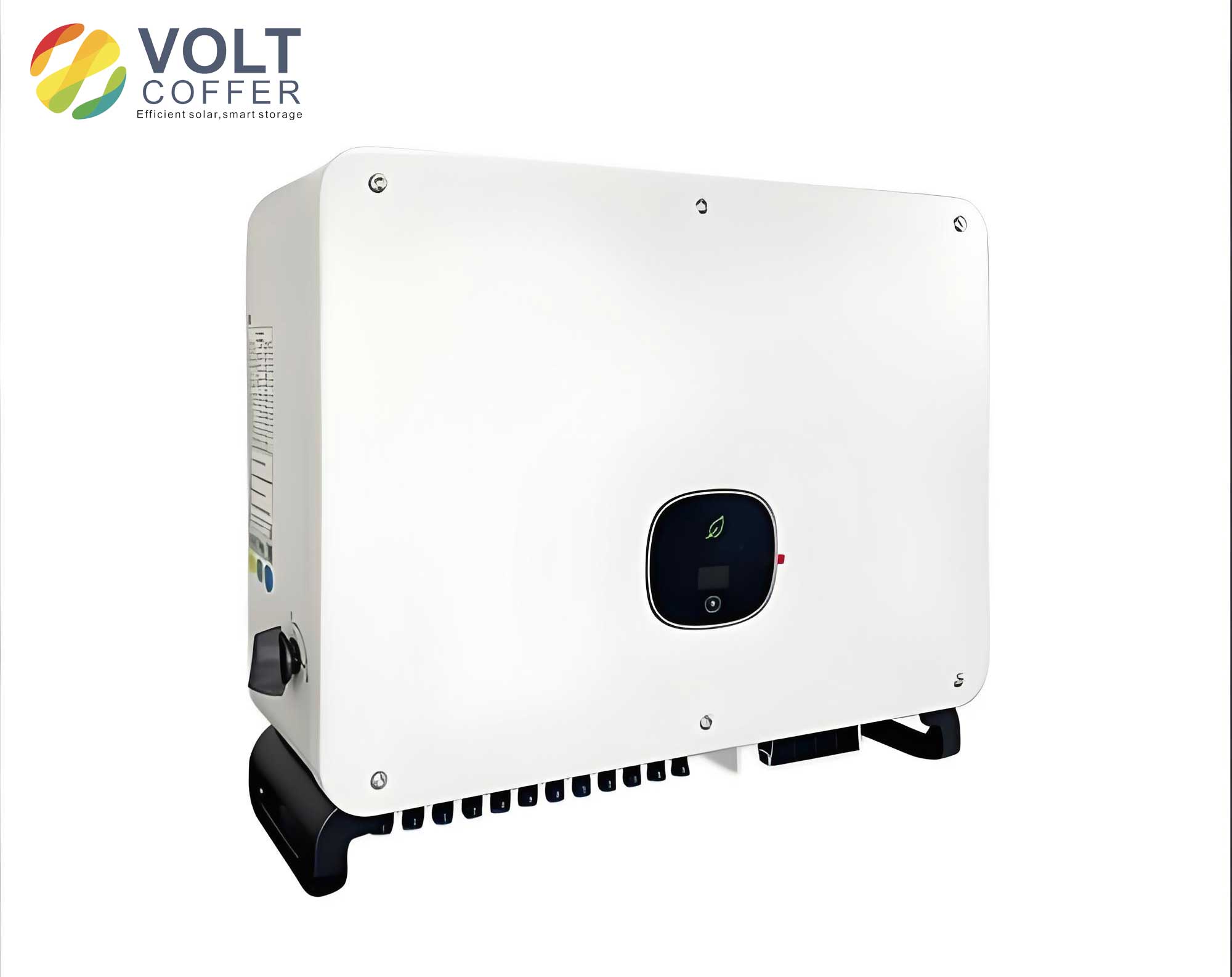
Traditional linear control strategies, such as PI-based current control in the synchronous reference frame (dq-frame), exhibit limitations in weak grids. Their performance degrades due to the phase lag introduced by the controller and computational delays, which can destabilize the system when coupled with grid-side inductance. This necessitates the development of advanced, robust control methodologies specifically designed for the utility interactive inverter operating under non-ideal grid conditions. This paper presents an integrated autonomous control method that synergizes Space Vector Pulse Width Modulation (SVPWM) with a virtual impedance correction strategy, enhanced by a Second-Order Generalized Integrator (SOGI)-based Phase-Locked Loop (PLL), to ensure stable and high-performance operation of the utility interactive inverter in weak grid scenarios.
System Architecture and Challenges for the Utility Interactive Inverter
The standard topology for a three-phase grid-connected PV system features a two-stage conversion: a DC-DC boost converter (often with Maximum Power Point Tracking, MPPT) and a DC-AC utility interactive inverter. This work focuses on the inverter stage, which is typically connected to the grid through an LCL filter. The LCL filter is preferred over simple L filters due to its superior high-frequency harmonic attenuation capability for a given total inductance, allowing for smaller and more cost-effective passive components.
The mathematical model of the three-phase LCL-type utility interactive inverter, including the grid impedance, forms the basis for stability analysis. The circuit equations in the three-phase (abc) stationary frame are given by:
$$ L_1 \frac{d}{dt} i_{1,abc} + R_1 i_{1,abc} = u_{inv,abc} – u_{C,abc} $$
$$ (L_2 + L_g) \frac{d}{dt} i_{2,abc} + R_2 i_{2,abc} = u_{C,abc} – u_{g,abc} $$
$$ i_{C,abc} = C \frac{d}{dt} u_{C,abc} = i_{1,abc} – i_{2,abc} $$
where \( i_{1,abc} \) and \( i_{2,abc} \) are the inverter-side and grid-side currents, \( u_{inv,abc} \) is the inverter bridge output voltage, \( u_{C,abc} \) is the capacitor voltage, \( u_{g,abc} \) is the grid voltage, \( L_1, R_1 \) are the inverter-side filter inductance and its parasitic resistance, \( L_2, R_2 \) are the grid-side filter inductance and its parasitic resistance, \( C \) is the filter capacitance, and \( L_g \) represents the grid inductance, which is significant in weak grid conditions. Transforming these equations into the synchronous rotating (dq) frame simplifies the control design by converting AC quantities into DC signals. The open-loop transfer function from the inverter voltage to the grid current is critical for stability analysis:
$$ G_{LCL}(s) = \frac{i_2(s)}{u_{inv}(s)} = \frac{1}{(L_1 L_2 + L_1 L_g + L_2 L_g) C s^3 + (L_1 + L_2 + L_g) s} = \frac{1}{L_{eq} s} \cdot \frac{\omega_r^2}{s^2 + \omega_r^2} $$
where \( L_{eq} = L_1 + L_2 + L_g \) and the resonant frequency \( \omega_r = \sqrt{\frac{L_1 + L_2 + L_g}{L_1 (L_2 + L_g) C}} \). The presence of \( L_g \) in these equations directly influences the resonant peak and the phase characteristics of the system. The primary challenges for the utility interactive inverter in a weak grid stem from two key interactions:
1. Impedance-Based Interaction: The variation of \( L_g \) alters the LCL filter resonance and the plant model seen by the current controller. A poorly damped resonance can be excited by the inverter’s switching harmonics or grid background harmonics, leading to instability.
2. Synchronization-Based Interaction: The PLL, essential for aligning the utility interactive inverter’s output with the grid, is sensitive to grid voltage disturbances. In a weak grid, the inverter’s current injection affects the Point of Common Coupling (PCC) voltage, which is fed back to the PLL. This creates a nonlinear feedback loop that can cause low-frequency oscillations.
The core challenge is to design a control system for the utility interactive inverter that remains stable and maintains high power quality despite these variable and adverse grid conditions.
Proposed Integrated Control Methodology
The proposed autonomous control method for the utility interactive inverter is built upon a multi-loop structure, enhanced with specialized algorithms to address weak-grid challenges. The overall control block diagram is conceptualized in the following architecture, combining the inner current control loop, the virtual impedance emulation block, and the advanced synchronization unit.
Current Control Loop with SVPWM and PR Regulators
The inner current loop is responsible for fast and accurate tracking of the grid current reference. A Proportional-Resonant (PR) controller in the stationary (αβ) frame is employed instead of a standard PI controller in the dq-frame. The PR controller provides high gain at the fundamental frequency (e.g., 50/60 Hz) with zero steady-state error for sinusoidal signals, eliminating the need for the dq transformation and its associated decoupling terms. The transfer function of a non-ideal PR controller is:
$$ G_{PR}(s) = K_p + \frac{2K_r \omega_c s}{s^2 + 2\omega_c s + \omega_0^2} $$
where \( K_p \) is the proportional gain, \( K_r \) is the resonant gain, \( \omega_0 \) is the fundamental angular frequency, and \( \omega_c \) is the cutoff bandwidth that provides robustness against minor frequency deviations. The output of the PR controller is the reference voltage vector in the αβ frame.
This voltage reference is then realized by the inverter bridge using Space Vector Pulse Width Modulation (SVPWM). SVPWM offers superior performance compared to sinusoidal PWM by providing a 15.47% higher maximum fundamental output voltage and lower total harmonic distortion (THD) for a given DC-link voltage. The SVPWM algorithm for the utility interactive inverter involves:
1. Sector identification of the reference voltage vector \( V_{ref}^{αβ} \).
2. Calculation of the dwell times for the two adjacent active voltage vectors and the zero vectors.
3. Generation of switching signals for the three inverter legs to synthesize the desired average voltage over a switching period.
The use of SVPWM enhances the DC-link voltage utilization and reduces current ripple, contributing to the stable operation of the utility interactive inverter.
Virtual Impedance Correction Strategy
To actively damp the LCL resonance and reshape the output impedance of the utility interactive inverter, a virtual impedance loop is incorporated. Instead of adding physical resistors (which cause losses), a virtual impedance is emulated in the control law. The concept is to modify the voltage reference from the current controller (\( u_{ref} \)) by subtracting a voltage drop equivalent to the current flowing through a virtual impedance \( Z_v(s) \):
$$ u_{mod} = u_{ref} – Z_v(s) \cdot i_2 $$
A common and effective choice for the utility interactive inverter is a virtual resistor in series with a virtual inductor, i.e., \( Z_v(s) = R_v + sL_v \). The high-pass filtered grid current is often used to avoid affecting the fundamental component. The transfer function of this virtual impedance emulation can be integrated into the control loop as a feedback term. This strategy actively dampens the resonant peak without physical losses. Furthermore, by carefully designing \( Z_v(s) \), the output impedance of the utility interactive inverter can be shaped to be more resistive or inductive at specific frequencies, which is beneficial for stabilizing the interaction with a weak, predominantly inductive grid.
Delay Compensation and Stability Enhancement
Digital control introduces inevitable delays: computational delay (\( T_d \)) and pulse-width modulation hold effect (\( 0.5T_{sw} \), where \( T_{sw} \) is the switching period). The total small-signal delay is approximately \( 1.5T_{sw} \). This delay introduces phase lag, which is particularly detrimental in weak grids as it reduces the phase margin of the current control loop. To mitigate this, a lead compensator or a prediction-based method can be embedded within the current controller. A simple yet effective approach is to advance the feedback current signal in the digital domain. The predicted current can be estimated using a first-order extrapolation:
$$ i_2^{pred}(k) = 2 \cdot i_2(k-1) – i_2(k-2) $$
This predicted current is then used in the PR controller and virtual impedance feedback loops, effectively reducing the phase lag caused by digital delay and enhancing the stability margin of the utility interactive inverter.
Advanced Synchronization with SOGI-PLL
A robust PLL is paramount for the utility interactive inverter. A dual Second-Order Generalized Integrator (SOGI)-based PLL is employed. A SOGI acts as an adaptive bandpass filter, generating orthogonal signals from an input. For a grid voltage \( v_g \), the SOGI structure produces outputs \( v’ \) and \( qv’ \) (90° shifted), which are perfectly locked to the input frequency. The transfer functions are:
$$ D(s) = \frac{v'(s)}{v_g(s)} = \frac{k \omega’ s}{s^2 + k \omega’ s + \omega’^2} $$
$$ Q(s) = \frac{qv'(s)}{v_g(s)} = \frac{k \omega’^2}{s^2 + k \omega’ s + \omega’^2} $$
where \( \omega’ \) is the estimated frequency and \( k \) is a damping factor. Two SOGIs are used in a structure to extract the positive-sequence component (\( v_{αβ}^+ \)) from the three-phase grid voltages, even under unbalanced or distorted conditions. This positive-sequence component is then fed into a standard PLL (e.g., a synchronous reference frame PLL) to extract a clean, accurate phase angle \( θ \). This SOGI-PLL provides excellent filtering of harmonics and rejection of negative-sequence components, ensuring stable synchronization for the utility interactive inverter during grid faults and disturbances.
Stability Analysis Framework
To validate the proposed control method for the utility interactive inverter, a stability analysis in the frequency domain is conducted. The impedance-based stability criterion (Nyquist criterion for the minor loop gain) is a powerful tool. The system can be viewed as an interaction between the output impedance of the utility interactive inverter \( Z_o(s) \) and the grid impedance \( Z_g(s) \). The minor loop gain is defined as:
$$ L_m(s) = \frac{Z_o(s)}{Z_g(s)} $$
For stability, the Nyquist plot of \( L_m(s) \) must not encircle the point (-1, j0). The proposed control method actively shapes \( Z_o(s) \). By incorporating the virtual impedance \( Z_v(s) \) and the predictive delay compensation, the magnitude and phase of \( Z_o(s) \) can be designed to avoid critical intersections with the typically inductive \( Z_g(s) \) across a wide frequency range, especially around the LCL resonance frequency and the crossover frequency of the current loop. The following table summarizes the key parameters of a sample utility interactive inverter system used for analysis.
| Parameter | Symbol | Value | Unit |
|---|---|---|---|
| Rated Power | S | 10 | kVA |
| Grid Voltage (L-L RMS) | V_g | 400 | V |
| Grid Frequency | f_0 | 50 | Hz |
| DC-Link Voltage | V_dc | 700 | V |
| Switching Frequency | f_sw | 10 | kHz |
| Inverter-side Inductor | L_1 | 2.5 | mH |
| Grid-side Inductor | L_2 | 1.0 | mH |
| Filter Capacitor | C_f | 10 | μF |
| Virtual Resistance | R_v | 5.0 | Ω |
| Virtual Inductance | L_v | 2.0 | mH |
| PR Controller K_p | K_p | 0.5 | – |
| PR Controller K_r | K_r | 50 | – |
Numerical Case Study and Performance Evaluation
A comprehensive simulation study is performed to compare the performance of the proposed method for the utility interactive inverter against two conventional strategies: a standard PI-based dq-current control (Method A) and a PR control with passive damping (Method B). The weak grid is simulated with a variable grid inductance \( L_g \) ranging from 0.5 mH to 8.0 mH. The key performance indicators (KPIs) evaluated are: Total Harmonic Distortion of grid current (THD_i), current tracking error, and stability under a sudden grid impedance change.
Case 1: Steady-State Performance under Moderate Weak Grid (L_g = 3.0 mH). The utility interactive inverter is operating at full power. The THD of the grid current is measured.
| Control Method | Current THD_i (%) | Fundamental Current Error (%) | Phase Lock Error (deg) |
|---|---|---|---|
| Proposed Method | 0.53 | 0.12 | 0.05 |
| Method B (PR + Passive Damp) | 0.91 | 0.31 | 0.15 |
| Method A (PI-dq) | 1.14 | 0.45 | 0.28* |
*The PI-dq method showed higher phase jitter under distorted grid voltage.
Case 2: Stability Under Grid Impedance Step Change. At time t = 0.3s, the grid inductance \( L_g \) is stepped from 2.0 mH to 6.0 mH, simulating a sudden weakening of the grid. The transient response of the grid current is analyzed. The proposed method, with its virtual impedance correction and delay compensation, exhibits a well-damped, stable transient with a settling time of less than 20 ms. Method B shows noticeable oscillation lasting ~50 ms, while Method A becomes marginally unstable, requiring intervention.
Case 3: Power Quality Under Unbalanced Grid Voltage Sag. A 20% voltage sag is applied to phase A for 5 cycles. The proposed SOGI-PLL maintains accurate synchronization, and the current controller limits the negative-sequence current injection as per grid codes, demonstrating the utility interactive inverter’s robustness to asymmetrical faults.
The stability margins can be quantitatively assessed using the loop gain analysis. The phase margin (PM) and gain margin (GM) of the current control loop for different grid impedances are calculated.
| Grid Inductance L_g (mH) | Proposed Method PM (deg) | Proposed Method GM (dB) | Method A PM (deg) |
|---|---|---|---|
| 1.0 (Strong Grid) | 65.2 | 12.5 | 58.1 |
| 3.0 (Weak Grid) | 48.7 | 10.1 | 32.5 |
| 6.0 (Very Weak Grid) | 41.5 | 8.3 | 15.8 |
Conclusion
Ensuring the stable operation of a utility interactive inverter in weak grid environments is a complex but essential challenge for modern power systems. This paper has presented a comprehensive, autonomous control solution that integrates advanced techniques tailored for this purpose. The method leverages the superior waveform quality of SVPWM, the precise tracking of stationary-frame PR controllers, and the robustness of a SOGI-based PLL. Its cornerstone is the active virtual impedance correction strategy, which dynamically reshapes the output impedance of the utility interactive inverter to actively damp resonances and ensure compatibility with a wide range of grid impedances. The additional compensation for digital control delays further enhances the stability margin.
The simulation-based case studies demonstrate the clear superiority of the proposed method over conventional approaches. It maintains exceptionally low current THD (below 0.6%) and minimal tracking error under steady-state weak grid conditions. More importantly, it provides robust stability during dynamic grid events, such as sudden changes in grid strength, where conventional methods may fail or exhibit poor performance. The utility interactive inverter equipped with this control strategy can therefore reliably support grid integration of photovoltaic resources, even in remote or underdeveloped network areas, contributing to grid stability and power quality. Future work will involve experimental validation on a hardware prototype and the extension of the control strategy to provide grid-supporting functions like frequency and voltage regulation, further enhancing the role of the utility interactive inverter as a key asset in the future smart grid.