
In the context of global energy transition and carbon neutrality goals, the rapid development of new energy-based power systems has placed significant emphasis on utility interactive inverter technology. As a core component, utility interactive inverters must ensure high-quality power injection into the grid, typically achieved through filters. Among these, LCL-type filters offer superior high-frequency filtering performance, reduced inductance requirements, and compact design compared to traditional L-type filters, optimizing efficiency and space. However, undamped LCL filters are prone to resonant peaks at their resonance frequency, compromising system stability and power quality. Thus, effective resonance suppression is crucial for maintaining performance in utility interactive inverters.
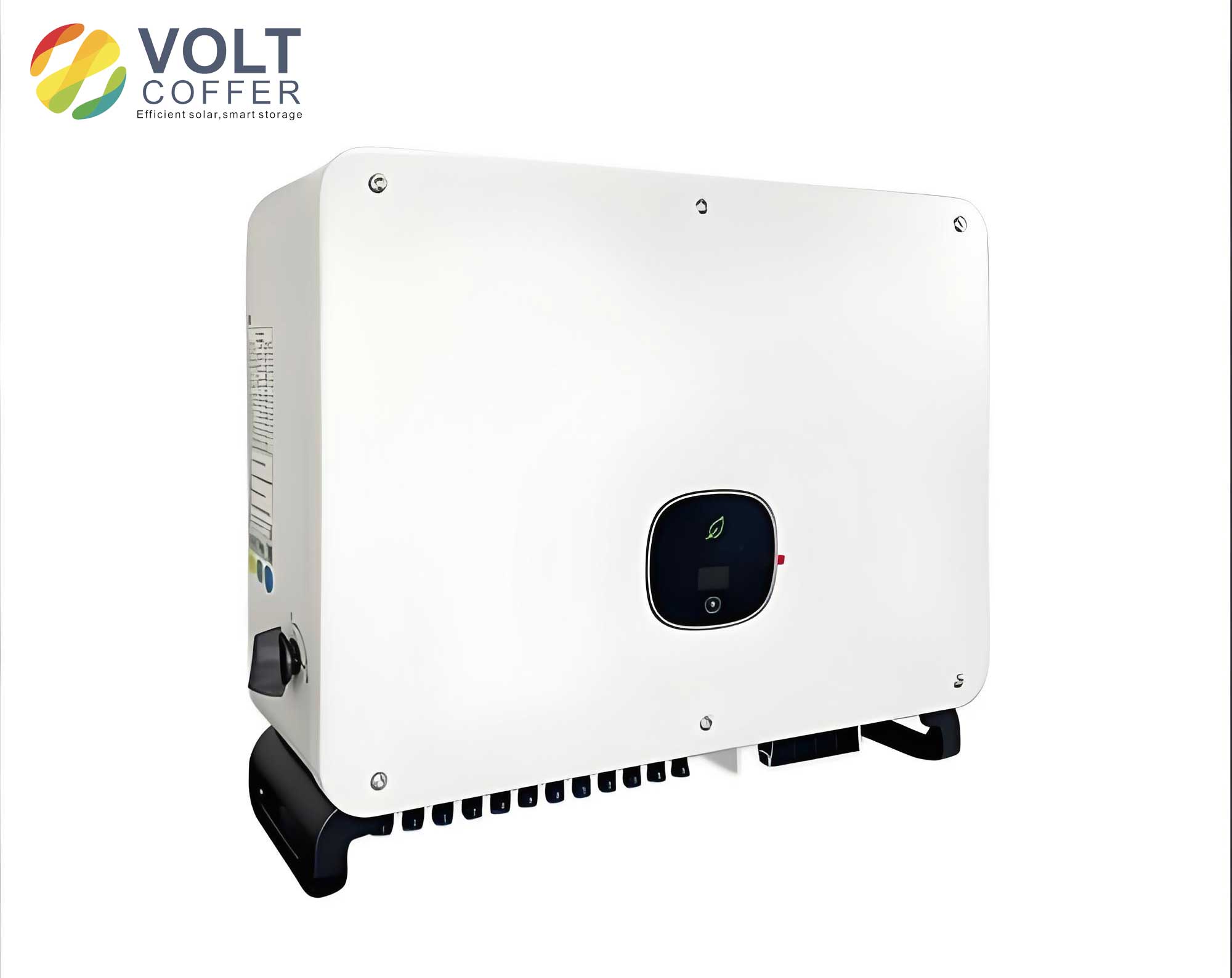
I explore a novel single-current dual-feedback closed-loop control strategy for utility interactive inverters with LCL filters, aiming to address resonant peaks without additional sensors. This strategy builds on traditional inverter-side single-current feedback by incorporating an active damping loop, effectively suppressing resonance while ensuring stability through virtual impedance analysis. The approach enables indirect control of grid current, aligning it with grid voltage in phase and frequency, thereby enhancing the performance of utility interactive inverters in renewable energy systems.
Traditional control methods for utility interactive inverters often rely on inverter-side current feedback, but this can lead to resonant spikes and instability. The open-loop gain for a conventional inverter-side current control system can be expressed as:
$$ T_o(s) = \frac{G_i(s) K_{PWM}}{L_1 L_2 C s^3 + (L_1 + L_2)s} $$
where \( G_i(s) \) is the PI controller, \( K_{PWM} \) is the PWM gain, \( L_1 \) and \( L_2 \) are the inverter-side and grid-side inductances, and \( C \) is the filter capacitance. This system exhibits a resonant peak at the frequency \( f_r = \frac{1}{2\pi\sqrt{L_{eq} C}} \), where \( L_{eq} \) is the equivalent inductance. For utility interactive inverters, this resonance can distort grid current and reduce power quality, necessitating damping techniques.
Active damping methods introduce feedback loops to emulate resistive damping without additional losses. My proposed strategy enhances this by using a dual-feedback loop that combines inverter-side current feedback with an active damping term. The control block diagram incorporates a sampling delay function \( G_d(s) = \exp(-1.5sT_s) \), where \( T_s \) is the sampling period. This delay is equivalently modeled as a virtual impedance in series with the inverter-side inductance, simplifying analysis for utility interactive inverters.
The equivalent virtual impedance \( Z_d(j\omega) \) is derived as:
$$ Z_d(j\omega) = H_i K_{PWM} [\cos(1.5\omega T_s) + j\sin(1.5\omega T_s)] $$
where \( H_i \) is the sensor gain. This can be split into a virtual resistance \( R_{eq}(\omega) \) and virtual inductance \( L_{eq}(\omega) \):
$$ R_{eq}(\omega) = H_i K_{PWM} \cos(1.5\omega T_s) $$
$$ L_{eq}(\omega) = \frac{H_i K_{PWM} \sin(1.5\omega T_s)}{\omega} $$
For utility interactive inverters, this virtual impedance modifies the LCL filter dynamics, allowing resonance suppression. The system’s open-loop gain with the improved control strategy becomes:
$$ T(s) = \frac{G_i(s) K_{PWM}}{L_{eq} L_2 C s^3 + L_2 C R_{eq} s^2 + (L_{eq} + L_2)s + R_{eq} + K} $$
where \( K = K_p + K_i/s \) represents the PI controller parameters. This formulation ensures that the resonance peak is damped without introducing反向谐振尖峰, common in traditional methods for utility interactive inverters.
To design optimal parameters for utility interactive inverters, I analyze the system’s damping ratio. The characteristic equation of the third-order system is:
$$ L_{eq} L_2 C s^3 + L_2 C R_{eq} s^2 + (L_{eq} + L_2)s + R_{eq} + K = 0 $$
The damping ratio \( \zeta \) is approximated as:
$$ \zeta \approx \frac{R_{eq}(\omega_r)}{2\omega_r L_{eq}(\omega_r)} $$
where \( \omega_r = \frac{1}{\sqrt{L_{eq} C}} \) is the resonant angular frequency. For utility interactive inverters, a damping ratio of 0.707 is typically targeted to balance response speed and stability. This leads to an optimal active damping feedback coefficient. The PI controller parameters are designed based on the crossover frequency \( \omega_c \), usually set to \( 0.3\omega_r \). The proportional gain \( K_p \) is given by:
$$ K_p = 0.3\omega_r (L_{eq} + L_2) / K_{PWM} $$
and the integral time constant is \( 10/\omega_c \). These calculations ensure robust performance for utility interactive inverters in varying grid conditions.
I summarize the key parameters for a typical utility interactive inverter in Table 1, highlighting the design considerations for resonance suppression.
| Parameter | Symbol | Value | Description |
|---|---|---|---|
| DC Link Voltage | \( V_{dc} \) | 200 V | Input voltage to inverter |
| Inverter-side Inductance | \( L_1 \) | 650 μH | Filter inductance on inverter side |
| Grid-side Inductance | \( L_2 \) | 200 μH | Filter inductance on grid side |
| Filter Capacitance | \( C \) | 20 μF | Capacitance in LCL filter |
| Grid Voltage | \( V_g \) | 110 V | RMS grid voltage |
| Switching Frequency | \( f_s \) | 20 kHz | PWM switching frequency |
| Resonant Frequency | \( f_r \) | 1.8 kHz | Calculated resonance of LCL filter |
| Active Damping Coefficient | \( H_i \) | 0.03 | Feedback gain for damping |
| PI Proportional Gain | \( K_p \) | 0.023 | Controller proportional term |
| PI Integral Gain | \( K_i \) | 0.002 | Controller integral term |
Stability analysis for utility interactive inverters is conducted using the Routh-Hurwitz criterion. The characteristic equation coefficients are evaluated to ensure all roots have negative real parts. For the third-order system, the Routh array is constructed as:
$$ \begin{array}{c|c}
s^3 & L_{eq} L_2 C \\
s^2 & L_2 C R_{eq} \\
s^1 & \frac{(L_{eq} + L_2)(L_2 C R_{eq}) – L_{eq} L_2 C (R_{eq} + K)}{L_2 C R_{eq}} \\
s^0 & R_{eq} + K \\
\end{array} $$
Stability requires all elements in the first column to be positive. For utility interactive inverters, this imposes constraints on \( K \) and \( R_{eq} \), ensuring the system remains stable under grid disturbances. The active damping feedback enhances stability by increasing the damping term, crucial for utility interactive inverters operating in weak grids.
Simulation results validate the control strategy for utility interactive inverters. Using MATLAB/Simulink, I model a 2 kW system with the parameters in Table 1. The grid current \( i_g \) quickly synchronizes with grid voltage \( v_g \) within 0.05 s, demonstrating fast dynamic response. The total harmonic distortion (THD) of the grid current is analyzed, achieving below 5%, as required by standards for utility interactive inverters. The inverter-side current \( i_1 \) indirectly controls \( i_g \), confirming the strategy’s effectiveness. Table 2 compares the performance of the proposed method with traditional approaches for utility interactive inverters.
| Control Strategy | Resonance Suppression | Sensor Count | THD (%) | Stability Margin |
|---|---|---|---|---|
| Traditional Inverter-side Current Feedback | Poor (peak at \( f_r \)) | 1 (inverter current) | >10 | Low |
| Capacitor Current Feedback | Good | 2 (inverter and capacitor currents) | <5 | Medium |
| Proposed Single-Current Dual-Feedback | Excellent (damped peak) | 1 (inverter current only) | <5 | High |
Experimental verification involves a 2 kW prototype utility interactive inverter using a TMS320F28335 DSP controller. The grid current waveform shows sinusoidal tracking with minimal distortion, and the THD measurement confirms compliance. The system’s robustness is tested under grid voltage variations, demonstrating reliable operation for utility interactive inverters in real-world scenarios.
The proposed control strategy offers significant advantages for utility interactive inverters. By leveraging a single current sensor and active damping feedback, it reduces cost and complexity while maintaining high performance. The virtual impedance model accounts for sampling delays, ensuring stability across frequencies. This approach is particularly beneficial for utility interactive inverters in distributed generation systems, where cost-effectiveness and reliability are paramount.
Further extensions for utility interactive inverters could include adaptive control for varying grid impedances or integration with advanced grid-support functions. The mathematical framework provided here serves as a foundation for optimizing utility interactive inverter designs in future renewable energy applications. In summary, this research contributes an economical and effective solution for enhancing the performance of utility interactive inverters with LCL filters, supporting the transition to sustainable power systems.