
In the pursuit of achieving the strategic goals of carbon peak and neutrality, the traditional power system, as a key sector on the supply side, must actively adapt in areas such as integrated energy services for “source-grid-load-storage” to facilitate a transition toward low-carbon energy upgrades. The new power system, characterized by “safety and efficiency, cleanliness and low carbon, flexibility and resilience, and intelligent integration,” leverages high penetration of renewable energy and power electronic devices to optimize resource allocation, promote efficient utilization of clean energy, and drive low-carbon and digital transformation. As clean and low-carbon development is the core objective of building this new system, non-fossil energy generation has seen rapid growth, with new energy sources gradually becoming the main increment in power generation. Among these, photovoltaic (PV) power generation technology has gained attention due to its economy, flexibility, and environmental friendliness. However, distributed PV inherently exhibits randomness, intermittency, and volatility, posing numerous risks to system stability upon grid integration.
To address the impacts of distributed PV integration on distribution network power flow, voltage distribution, and other aspects, control strategies based on active and reactive power adjustments by distributed PV for voltage regulation in distribution networks have attracted widespread attention. Active control primarily involves methods such as PV active power curtailment and energy storage active power regulation to achieve rapid power absorption. Reactive control, on the other hand, can realize reactive power compensation through phase-angle rotation of various converters, among which the Distribution Static Compensator (DSTATCOM) is a relatively effective device. However, conventional DSTATCOM typically only offers single reactive compensation capability. When node voltage is influenced by active power, its voltage regulation ability diminishes. Moreover, the distinct characteristics of voltage fluctuations caused by distributed PV output impose higher demands on the compensation capability of DSTATCOM in distribution networks. To improve power quality under distributed PV integration and enhance the flexibility of voltage regulation in distribution networks, an increasing number of control methods are being applied to dynamic voltage regulation in distribution network operation control.
In this context, I propose a robust adaptive control strategy for high-proportion distributed PV distribution networks that considers the coordination of DSTATCOM and on-grid inverters. This strategy aims to address power quality issues arising from high-penetration distributed PV access, ensuring safe and stable operation of the new power system. The approach involves establishing a unified model for reactive voltage control of DSTATCOM and on-grid inverters, developing an uncertain system model for distribution network voltage control that accounts for randomness in system output and load, designing a robust voltage control strategy using sensitivity analysis and robust H∞ performance constraints, and incorporating adaptive optimization with active power curtailment. The effectiveness of the proposed strategy is validated through simulation on an IEEE 33-node system model containing DSTATCOM and high-proportion distributed PV.
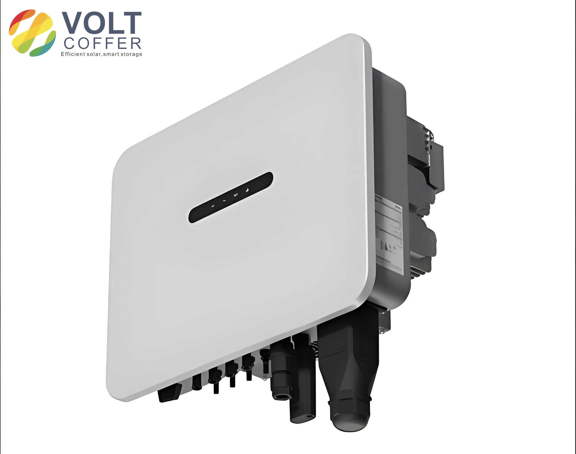
The integration of high-penetration distributed PV transforms distribution networks from passive to active systems. The dispersed access of distributed PV not only affects the voltage at the connected nodes but also influences the overall voltage distribution due to factors like start-stop operations and generation fluctuations. Influenced by uncertain natural conditions such as sunlight and temperature, large-scale grid integration of distributed PV can lead to severe power quality issues like voltage fluctuations, voltage limit violations, and increased harmonics, posing significant challenges to closed-loop dynamic voltage feedback control in distribution networks. DSTATCOM, as an advanced dynamic reactive power compensation device based on inverter principles, offers functions such as harmonic compensation and imbalance mitigation, making it a crucial technical means to support voltage levels in distribution networks with high-penetration distributed PV. Meanwhile, the on-grid inverter for distributed PV integration possesses certain reactive voltage support capabilities, serving as a potential voltage and reactive power regulation resource. Typically operating at unity power factor, the on-grid inverter can be utilized for reactive power adjustment to mitigate voltage issues at the point of common coupling (PCC).
To facilitate the analysis of the coordinated support role of DSTATCOM and on-grid inverters on distribution network voltage, I first establish a unified model for their reactive voltage control. For a single distributed PV grid-connected system, the simplified model includes the grid voltage, line impedance, and the on-grid inverter output. The voltage at the PCC can be expressed as:
$$U_P = U_S + \frac{(P_D – \Delta P)R_S + (Q_D + Q_C – \Delta Q)X_S}{U_S}$$
where \(U_P\) is the PCC voltage, \(U_S\) is the grid voltage, \(P_D\) and \(Q_D\) are the active and reactive power outputs of the PV on-grid inverter, respectively, \(\Delta P\) and \(\Delta Q\) are the active and reactive power losses on the line and transformer impedance, \(R_S\) and \(X_S\) are the line resistance and reactance, and \(Q_C\) is the reactive output of the compensation device. By coordinately controlling the reactive input of the inverter and reactive compensation devices, voltage limit violations at the PCC due to PV integration can be resolved.
For the on-grid inverter, most distributed PV systems employ PQ control for grid connection, where voltage and frequency are primarily supported by the main grid. Under PQ control, the three-phase fundamental voltage of the inverter is transformed into the dq rotating coordinate system:
$$
\begin{bmatrix}
E_d \\
E_q
\end{bmatrix}
= T_{abc \to dq}
\begin{bmatrix}
E_a \\
E_b \\
E_c
\end{bmatrix}
=
\begin{bmatrix}
E_m \\
0
\end{bmatrix}
$$
where \(T_{abc \to dq}\) is the transformation matrix from abc to dq coordinates, \(E_d\) and \(E_q\) are the d-axis and q-axis components of the inverter voltage, and \(E_m\) is the phase voltage amplitude. The relationship between the voltage and current at both ends of the grid-connected line is given by:
$$
U_{Fd} = E_m + R i_d + L’ \left( \frac{di_d}{dt} – \omega i_q \right)
$$
$$
U_{Fq} = R i_q + L’ \frac{di_q}{dt} + \omega i_q
$$
where \(U_{Fd}\) and \(U_{Fq}\) are the d-axis and q-axis components of the grid voltage, \(i_d\) and \(i_q\) are the d-axis and q-axis components of the grid current, \(R\) is the line resistance, \(L’\) is the sum of the line inductance and filter inductance, and \(\omega\) is the angular speed. The reactive power injected into the grid by the i-th PV can be derived from the equivalent output model:
$$
Q_i = \frac{U_i U_j}{Z_{ij}} \sin(\varphi_{Z_{ij}} – \phi_{ij}) – \frac{U_j^2}{Z_{ij}} \sin \varphi_{Z_{ij}}
$$
where \(U_i\) and \(\phi_i\) are the voltage amplitude and phase of the i-th on-grid inverter output, \(U_j\) and \(\phi_j\) are the voltage amplitude and phase at the PCC j, \(Z_{ij}\) is the impedance between the inverter i and PCC j, \(\varphi_{Z_{ij}}\) is the impedance angle, and \(\phi_{ij}\) is the phase difference. Linearizing around a steady-state operating point yields:
$$
\Delta Q_i = \frac{\partial Q_i}{\partial \phi_i} \Delta \phi_i + \frac{\partial Q_i}{\partial U_i} \Delta U_i = S_{Q\phi} \Delta \phi_i + S_{QU} \Delta U_i
$$
where \(\Delta Q_i\) is the change in reactive power, \(\Delta \phi_i\) and \(\Delta U_i\) are changes in phase and voltage, and \(S_{Q\phi}\) and \(S_{QU}\) are coupling coefficients. Ignoring the power angle effect, the reactive change is positively correlated with voltage change.
For DSTATCOM, it is represented as a variable controlled voltage source connected in parallel to the grid via a current-limiting reactance or coupling transformer. The injected active and reactive power are:
$$
P_{sh} = \frac{U_{sh} U_P}{X_{sh}} \sin(\phi_{sh} – \beta)
$$
$$
Q_{sh} = \frac{U_{sh}^2}{X_{sh}} – \frac{U_{sh} U_P}{X_{sh}} \cos(\phi_{sh} – \beta)
$$
where \(U_{sh}\) is the DSTATCOM inverter output voltage amplitude, \(X_{sh}\) is the reactance between the inverter and PCC, \(\phi_{sh}\) is the line impedance angle, and \(\beta\) is the phase difference. Similarly, linearizing gives:
$$
\Delta Q_{sh} = \frac{\partial Q_{sh}}{\partial \phi_{sh}} \Delta \phi_{sh} + \frac{\partial Q_{sh}}{\partial U_{sh}} \Delta U_{sh} = S_{Q\phi} \Delta \phi_{sh} + S_{QU} \Delta U_{sh}
$$
Unifying the models for the on-grid inverter and DSTATCOM, the control model for the n-th device in the system can be expressed as:
$$
\dot{U}_n = a_n U_n + b_n u_n + f, \quad n \in S_2
$$
where \(U_n\) is the voltage, \(u_n = \dot{Q}_n\) is the reactive power deviation set as the input, \(a_n\) and \(b_n\) are control coefficients, and \(f\) represents disturbance terms. This unified model enables coordinated reactive voltage control across multiple devices.
In distribution networks with multiple distributed PV integrations, node voltage is influenced not only by the local on-grid inverter but also by the injected power from other distributed PV sources. Therefore, I introduce node voltage sensitivity to characterize the degree of influence of grid voltage and other PV injections on the voltage at the PV access node. The voltage at the n-th control model access node is:
$$
U_n = U’_n + \sum_{m \in S_2, m \neq n} K^{UP}_{nm} P_m + \sum_{m \in S_2, m \neq n} K^{UQ}_{nm} Q_m
$$
where \(U’_n\) is the voltage at node n under steady-state conditions, \(P_m\) and \(Q_m\) are the active and reactive power injected by PV at node m, and \(K^{UP}_{nm}\) and \(K^{UQ}_{nm}\) are the voltage-active and voltage-reactive sensitivity coefficients, respectively. Treating the active power influence on voltage as an uncertainty, the change in voltage can be expressed as:
$$
\Delta U_n = \Delta U’_n + f(\Delta P_n) + \sum_{m \in S_2, m \neq n} \frac{K^{UQ}_{nm}}{K^{UQ}_{mm}} \Delta Q_m
$$
where \(f(\Delta P_n)\) represents the disturbance from active power changes. Combining with the unified control model, the overall control model for the distribution network with N control objects is established as:
$$
\dot{x}(t) = A x(t) + B_1 u(t) + B_2 w(t)
$$
where \(x(t) = [\Delta U_1, \Delta U_2, \ldots, \Delta U_N]^T\) is the state variable, \(u(t) = [\Delta Q_1, \Delta Q_2, \ldots, \Delta Q_N]^T\) is the control input, \(w(t) = [f(\Delta P_1), f(\Delta P_2), \ldots, f(\Delta P_N)]^T\) is the disturbance from active power, and matrices A and B1 are influenced by voltage sensitivities between controlled nodes and other nodes, with B2 being the identity matrix.
Considering uncertainties in practical distribution network operation, such as changes in node voltages and line parameters, which cause perturbations in matrices A and B1, the model is rewritten as an uncertain system:
$$
\dot{x}(t) = (A + \Delta A(t)) x(t) + (B_1 + \Delta B_1(t)) u(t) + B_2 w(t)
$$
$$
z(t) = C x(t)
$$
where \(\Delta A(t)\) and \(\Delta B_1(t)\) represent bounded influences from uncertainties, satisfying:
$$
[\Delta A(t) \quad \Delta B_1(t)] = H \Sigma(t) [F_a \quad F_b]
$$
with H, F_a, F_b being known matrices of appropriate dimensions, and \(\Sigma(t)\) being an unknown function matrix belonging to the set \(\Omega = \{ \Sigma(t) | \Sigma^T(t) \Sigma(t) \leq I, \forall t \}\).
To design a robust controller for this system, I consider a state feedback controller of the form \(u(t) = K x(t)\), where K is the feedback matrix. The closed-loop system should be quadratically stable for all parameter uncertainties and satisfy the specified H∞ performance constraint:
$$
\| C [sI – (A + B_1 K)]^{-1} B_2 \|_{\infty} < \gamma
$$
where \(\gamma\) is a key parameter measuring system robustness. For a given \(\gamma > 0\), if there exist positive definite symmetric matrices X and matrix Z satisfying the linear matrix inequality (LMI):
$$
\begin{bmatrix}
\Xi & H & B_2 & Z^T F_b^T + X F_a^T & Z^T D^T + X C^T \\
H^T & -I & 0 & 0 & 0 \\
B_2^T & 0 & -\gamma^2 I & 0 & 0 \\
F_b Z + F_a X & 0 & 0 & -I & 0 \\
C X + D Z & 0 & 0 & 0 & -I
\end{bmatrix} < 0
$$
with \(\Xi = (Z^T B_1^T + X A^T) + (B_1 Z + A X)\), then the state feedback gain matrix is given by \(K = Z X^{-1}\). To maintain node voltage within the allowable operating range of the distribution network, the reference voltage \(U_{ref}\) from the upper grid is chosen, and the voltage state variable is set as \(x = \Delta U = U_{ref} – U_{actual}\). Solving the LMI using toolbox yields K, and the control input \(u = K x = \Delta Q\) is obtained. Integrating gives the reference input \(\Delta Q_{ref}\) for the on-grid inverter and DSTATCOM, achieving a unified robust control strategy.
In practical operation, distributed PV should not only maximize power output but also meet the grid connection standard with power factor adjustable within the range (-0.98 to 0.98). The robust controller designed above does not consider PV operation constraints. If the system reactive power deficit is large, the reactive demand may exceed the reactive capacity of the on-grid inverter, leading to reactive overrun issues even though voltage can be quickly restored. Therefore, I propose an adaptive control adjustment that, in addition to addressing power quality issues, curtails the active output of some inverters based on their current reactive output to meet the reactive demand at the PCC.
Considering the capacity constraints of the on-grid inverter, the relationship between output reactive and active power is:
$$
Q = \sqrt{S^2 – P^2} = P \tan \phi
$$
where S is the apparent power and \(\phi\) is the power factor angle. The reactive power output range during normal operation is:
$$
-\sqrt{S^2 – P^2} \leq Q \leq \sqrt{S^2 – P^2}
$$
Defining the reactive adaptive coefficient for the inverter as:
$$
\mu_i = \frac{Q_i^{\text{max}}}{\sqrt{S^2 – P_i^2}}
$$
where \(Q_i^{\text{max}}\) is the maximum reactive output required by the i-th distributed PV at active power output \(P_i\). If \(\mu_i < 1\), no active coordination for voltage regulation is needed at that node; if \(\mu_i \geq 1\), adaptive active coordination is performed. The adaptive control adjustment is designed as:
$$
Q_i(t) = \sqrt{S^2 – P_i^2(t)}
$$
$$
Q_i(t-1) + \Delta Q_i(t) = Q_i(t) + \mu_i \Delta Q’_i(t)
$$
$$
\Delta P_i(t) = \alpha_i \mu_i \Delta Q’_i(t)
$$
$$
\lim_{t \to \infty} \Delta Q’_i = 0, \quad \lim_{t \to \infty} \Delta P_i(t) = 0
$$
where \(\alpha_i\) is a coefficient from the voltage sensitivity matrix, \(\Delta P_i\) is the active power curtailment, and \(\Delta Q’_i\) is the reactive overrun. When the inverter output reaches its limit, the adaptive control strategy adjusts the results from the robust controller by appropriately curtailing PV active power, achieving active coordination for voltage regulation and providing dynamic reactive support that aligns with practical scenarios.
The proposed robust adaptive control strategy requires collecting voltage signals from various distributed PV and DSTATCOM in the distribution network. In practical engineering, devices are often far apart, making simultaneous signal acquisition challenging, and controller performance may be limited by factors such as computational capability and the number of converters. Therefore, future research could consider partitioning the distribution network into different zones. Most literature employs delay links or synchronous clock methods for optimization. For instance, one study designed a sampling delay compensation method considering transmission delay and switch delay for shared sampled value message information. Another proposed a distribution network operation data monitoring device design based on synchronization vectors. Initially, voltage vulnerable nodes in the distribution network are selected using node voltage sensitivity analysis, and DSTATCOM reactive compensation devices are connected at these nodes. Then, the distribution network is partitioned into different zones based on source-load spatiotemporal characteristics, with edge computing units configured in each zone to implement the robust adaptive control strategy within the zone. Finally, upper-layer optimization achieves coordination between zones, ensuring the entire feeder voltage operates within a reasonable range. The number of power electronic converters controlled by the robust adaptive controller in each zone can be adapted based on the edge computing unit.
To validate the proposed strategy, I conducted simulation analysis using MATLAB/Simulink to build a high-proportion distributed PV integrated IEEE 33-node distribution network model. The system has an active load of 2229 kW and a reactive load of 1380 kvar. Ten sets of distributed PV are connected, with four sets at nodes 10, 11, 21, and 30 being uncontrollable distributed PV, and the remaining six sets being controllable distributed PV. Each distributed PV has a maximum output power of 350 kW, and the on-grid inverter capacity is 400 kVA. Based on node voltage sensitivity analysis, the parameter variation ranges for ΔA and ΔB1 are between -0.28 and 0.02. Using the LMI toolbox to solve the linear inequality, the state feedback matrix K is obtained, and the next control command is \(u = K x = \Delta Q\).
In the simulation, without any control, when all ten sets of distributed PV are投入 at full power of 350 kW at t=0.5 s, and load shedding occurs at nodes 7, 8, 16, 20, 24, 25, 27, 28, and 30 at t=1.0 s, significant voltage limit violations occur due to PV integration and reduced load. The voltage changes across all system nodes show rapid increases at t=0.5 s, with most node voltages exceeding the upper critical limit (1.05 per unit) instantly upon PV access. At t=1.0 s, load shedding exacerbates voltage limit violations, posing serious threats to the safe and stable operation of the distribution network.
With the coordination of DSTATCOM and on-grid inverters under the robust voltage control strategy, a DSTATCOM with a capacity of 1 Mvar is connected at node 15. The proposed robust coordinated control strategy is configured for the DSTATCOM and controllable distributed PV in the system. The node voltage changes show that robust coordinated control enables rapid voltage recovery when system changes occur, with most node voltages maintained within the qualified voltage range (0.95–1.05 per unit) at the moment of PV integration. However, if load突变 occurs in the system, some node voltages may still exceed the upper limit, indicating that safe and stable system operation cannot be fully guaranteed. This strategy primarily increases the reactive output of distributed PV to stabilize system voltage within the qualified range. Yet, to keep node voltage within a good voltage range (0.95–1.05 per unit), distributed PV need to output more reactive power, leading to reactive overrun issues. Therefore, it is essential to consider PV output limits and configure an adaptive control strategy to curtail active power of distributed PV, increasing reactive power output.
Considering the output constraints of distributed PV in practical operation, the robust adaptive control strategy is configured in the simulation model. Under this control strategy, controllable distributed PV in the distribution network achieve dynamic feedback control through unified robust adaptive compensation, with all node voltages maintained within the good voltage range (0.95–1.05 per unit). Even after PV fluctuations and load shedding, the system can achieve rapid voltage recovery, maintaining safe and stable operation of the distribution network. The robust adaptive control strategy more fully considers the required voltage range and operational constraints of the entire system, making distributed PV output more aligned with practical situations and effectively avoiding adverse effects from reactive overrun.
The following table summarizes the output of controllable distributed PV under the robust control strategy and the robust adaptive control strategy:
| PV Serial Number | Active Output (kW) under Robust Control | Reactive Output (kvar) under Robust Control | Active Output (kW) under Robust Adaptive Control | Reactive Output (kvar) under Robust Adaptive Control |
|---|---|---|---|---|
| 3 | 350 | -193 | 334 | -220 |
| 4 | 348 | -197 | 330 | -226 |
| 5 | 347 | -199 | 329 | -227 |
| 6 | 347 | -199 | 313 | -249 |
| 8 | 350 | -103 | 350 | -114 |
| 10 | 350 | -120 | 350 | -141 |
Under the robust adaptive control strategy, uncontrollable distributed PV output rated active power, while controllable distributed PV, based on the robust control strategy design, increase reactive output to restore system node voltage. The adaptive constraint’s active curtailment plan effectively avoids reactive overrun issues. The output of the ten sets of distributed PV under the robust adaptive control strategy shows that active power curtailment is applied where needed to enable higher reactive support.
Randomly selecting voltage values from 14 nodes in the IEEE 33-node system for comparison, including nodes without distributed PV, nodes with uncontrollable distributed PV, and nodes with controllable distributed PV, and calculating cumulative voltage deviation based on the standard voltage, the robust adaptive control considers the output limits of distributed PV in practical situations and performs active coordination for voltage regulation. Compared to the单一 robust control strategy, its average deviation is reduced, and voltage limit violations are significantly improved. The table below presents part of the node voltages under different strategies:
| Node Serial Number | Voltage (per unit) without Strategy | Voltage (per unit) with Robust Control | Voltage (per unit) with Robust Adaptive Control |
|---|---|---|---|
| 5 | 1.0201 | 1.0195 | 1.0069 |
| 7 | 1.0282 | 1.0255 | 1.0104 |
| 8 | 1.0378 | 1.0325 | 1.0131 |
| 10 | 1.0499 | 1.0415 | 1.0169 |
| 12 | 1.0624 | 1.0493 | 1.0236 |
| 13 | 1.0651 | 1.0500 | 1.0255 |
| 14 | 1.0684 | 1.0514 | 1.0262 |
| 15 | 1.0710 | 1.0521 | 1.0321 |
| 16 | 1.0760 | 1.0543 | 1.0329 |
| 17 | 1.0772 | 1.0550 | 1.0119 |
| 21 | 1.0036 | 1.0032 | 1.0020 |
| 23 | 1.0038 | 1.0021 | 1.0018 |
| 27 | 1.0165 | 1.0113 | 0.9962 |
| 30 | 1.0228 | 1.0101 | 0.9931 |
| Cumulative Voltage Deviation | 0.1885 | 0.1425 | 0.0695 |
In conclusion, based on dynamic voltage robust control technology, I propose a robust control strategy for high-proportion distributed PV distribution networks that considers the coordination of DSTATCOM and on-grid inverters. A unified voltage control model for DSTATCOM and on-grid inverters is established, taking into account the mutual influence between nodes and distributed PV output constraints. A dynamic voltage robust adaptive control strategy is designed, and its feasibility is verified through simulation analysis. The findings are as follows: Firstly, compared to a single on-grid inverter reactive control model, the proposed reactive voltage control model for DSTATCOM and on-grid inverters can more safely and quickly stabilize system node voltage, addressing voltage limit violations caused by PV integration and load changes. Secondly, this robust control strategy considers the interactions between nodes, exhibiting robustness to system parameter uncertainties. It also accounts for the actual output of distributed PV, proposing a robust adaptive control strategy that achieves active coordination for voltage regulation and avoids reactive overrun issues. The on-grid inverter plays a pivotal role in this coordinated framework, enabling effective voltage support through both reactive and active power adjustments. Future work will focus on practical implementation aspects such as network partitioning, edge computing deployment, and real-time communication protocols to enhance the scalability and reliability of the proposed control strategy in large-scale distribution networks with high penetration of renewable energy sources.