
In recent years, the increasing integration of distributed generation systems, such as photovoltaic (PV) and wind power, has led to a gradual weakening of the grid, characterized by widely varying grid impedance. This variation can adversely affect the stability margin of on-grid inverter systems and may induce resonance between grid-connected inverters and the grid in multi-inverter parallel configurations. To address these challenges, we propose a novel multi-functional on-grid inverter that simultaneously performs grid-connected power generation and active resonance damping. This inverter is based on an energy-stored quasi-Z-source topology, which offers advantages like single-stage buck-boost capability, shoot-through immunity, and high reliability, while its impedance network capacitors can buffer reactive energy. In this paper, we present a comprehensive design methodology, including circuit parameter guidelines, control strategies accounting for phase-locked loop (PLL) effects, and parameter tuning methods. The control strategy enhances system stability by increasing the phase margin of the original port impedance through phase-lag compensation in the capacitor current feedback loop. Additionally, a virtual impedance is constructed at the output to damp resonances within a target frequency range in multi-on-grid inverter systems. Experimental results validate the feasibility and effectiveness of the proposed multi-functional on-grid inverter, demonstrating its robustness under varying grid conditions.
The proliferation of renewable energy sources has transformed power grids, making them more susceptible to instability due to fluctuating grid impedance. On-grid inverters, which interface distributed generation with the grid, must maintain stability and power quality under such conditions. In multi-on-grid inverter systems, interactions between inverter output impedances and grid impedance can lead to resonant peaks, potentially causing harmonic distortion or even system failure. Traditional solutions include modifying inverter control strategies to reshape output impedance or adding external damping devices, but these approaches often lack generality or increase cost and volume. To overcome these limitations, we integrate the active damper function into a grid-connected inverter, creating a multi-functional on-grid inverter that operates in both power generation and resonance suppression modes without mode switching. This integration reduces system footprint and cost while improving reliability. Our work focuses on a multi-functional on-grid inverter based on an energy-stored quasi-Z-source inverter, which inherently includes储能 elements to smooth PV power fluctuations. We delve into the detailed design of circuit parameters, control loops, and virtual impedance implementation, ensuring the on-grid inverter remains stable across a wide range of grid impedances.
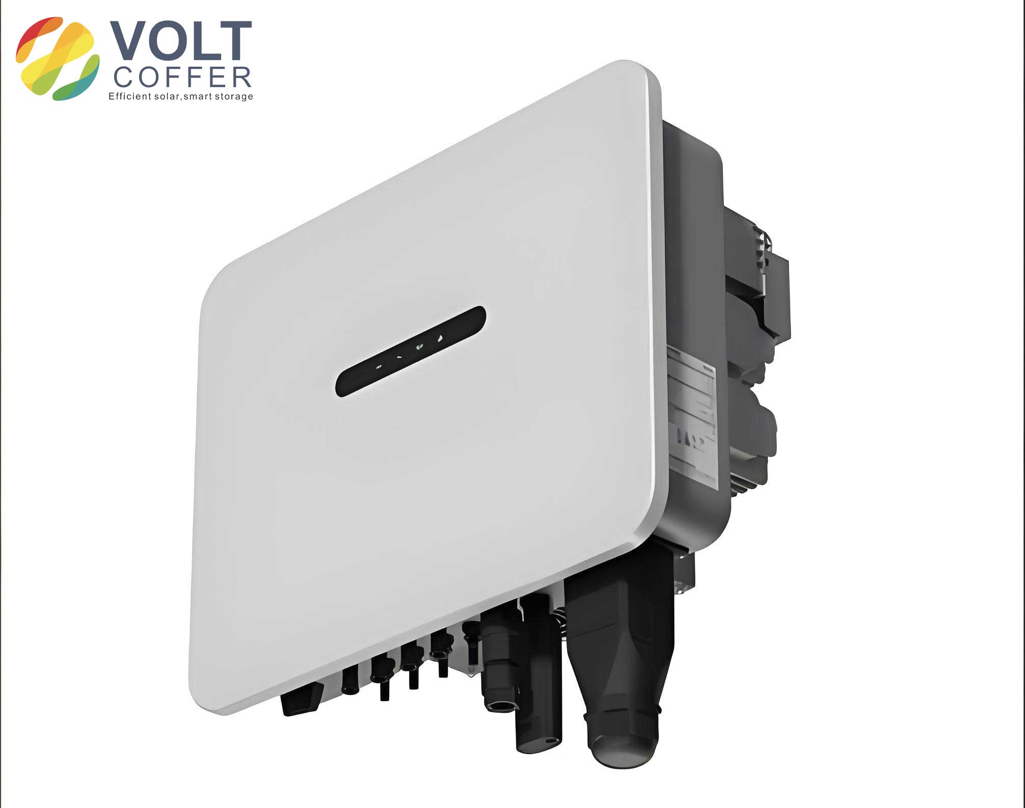
The structure of the multi-functional on-grid inverter is derived from the energy-stored quasi-Z-source inverter, as shown in the system configuration where it connects in parallel with other PV on-grid inverters at the point of common coupling (PCC). The grid impedance is denoted as \(Z_g\). The inverter operates in shoot-through and non-shoot-through states. During shoot-through, diodes block, and inductors charge while capacitors discharge; during non-shoot-through, diodes conduct, and capacitors charge while inductors discharge. Using voltage-second balance, the capacitor voltages and DC-link voltage can be expressed as functions of the shoot-through duty cycle \(D_0\) and PV voltage \(U_{PV}\). To suppress resonance between on-grid inverters and the grid, the capacity \(S_N\) of the multi-functional on-grid inverter must satisfy:
$$S_N \geq \frac{3 \lambda_{k \text{max}} U_g^2}{R_{V,\text{min}}}$$
where \(\lambda_{k \text{max}}\) is the maximum ratio of resonant component to fundamental frequency in PCC voltage, \(U_g\) is the RMS phase voltage, and \(R_{V,\text{min}}\) is the minimum virtual resistance emulated by the active damper function. Grid strength is often characterized by the short-circuit ratio (SCR), and the maximum grid inductance \(L_{g \text{max}}\) relates to the total output power \(P_{\text{out}}\) of the multi-on-grid inverter system:
$$L_{g \text{max}} \geq \frac{3U_g^2}{K_{\text{SCR}} \cdot 2\pi f_0 \cdot P_{\text{out}}}$$
where \(K_{\text{SCR}}\) is the short-circuit current ratio and \(f_0\) is the fundamental frequency. Based on these, the rated capacity of the multi-functional on-grid inverter is selected.
For the impedance network parameters, the energy-stored inductance \(L\) is designed to suppress high-frequency current ripple, avoid resonance with capacitors, and ensure continuous inductor current. Using ZSVM2 modulation, the inductance must satisfy:
$$L \geq \frac{3 D_0 U_m}{2 \Delta i_L f_s}$$
where \(U_m\) is the peak phase voltage, \(f_s\) is the switching frequency, and \(\Delta i_L\) is the maximum current ripple. To prevent resonance with capacitance \(C\):
$$L \gg \frac{1}{4\pi^2 f_s^2 C}$$
For continuous conduction:
$$L > \frac{3 D_0 U_m U_{PV} \eta}{2f_s \left( \sqrt{6}U_m I_o – 2 I_o U_{PV} \eta \right)}$$
where \(\eta\) is the inverter efficiency and \(I_o\) is the rated output current per phase. The inductance \(L\) is chosen as the maximum value from these constraints. The energy-stored capacitance \(C\) must meet requirements for voltage ripple suppression and DC-link voltage fluctuation limits for the active damper function. The series combination of capacitors \(C_1\) and \(C_2\) acts as the DC-link capacitor \(C_{\text{dc}}\). For voltage ripple limitation:
$$C_k \geq \frac{I_{L2} \left| 3U_m – U_{PV}(1-2D_0) \right|}{2\gamma f_s U_{C_k} U_{PV}}$$
where \(\gamma\) is the voltage ripple coefficient. Considering power pulsation due to harmonic currents, the minimum \(C_{\text{dc}}\) is derived from energy balance:
$$C_{\text{dc}} > \begin{cases}
\frac{6K_k U_1 I_1}{\omega_0 (k+1) \cdot U_{\text{PN}} \cdot \Delta U_{\text{PN}}}, & k=6m-1, m=1,2,3,\ldots \\
\frac{6K_k U_1 I_1}{\omega_0 (k-1) \cdot U_{\text{PN}} \cdot \Delta U_{\text{PN}}}, & k=6m+1, m=1,2,3,\ldots
\end{cases}$$
where \(K_k\) is the ratio of harmonic current to fundamental, \(U_{\text{PN}}\) is the average DC-link voltage, and \(\Delta U_{\text{PN}}\) is the voltage fluctuation. The capacitance is selected based on the worst-case harmonic order.
The LCL filter parameters for the multi-functional on-grid inverter are designed to meet filtering requirements and target resonance damping. The inverter-side inductance \(L_{f1}\) is determined by current ripple limitation:
$$L_{f1} \geq \frac{U_m T_s}{2\sqrt{3} \varepsilon_{L_{f1}} I_o}$$
where \(\varepsilon_{L_{f1}}\) is the current ripple coefficient. The total inductance \(L_{\text{sum}} = L_{f1} + L_{f2}\) must limit current slew rate for the active damper function:
$$L_{\text{sum}} \leq \min \left( \frac{U_L}{2 \omega_{\text{res}} I_k}, \frac{U_L}{2 \omega_0 I_o} \right)$$
with \(U_L = U_{\text{PN}}/\sqrt{3} – 1.1 \times U_m\) and \(\omega_{\text{res}}\) as the highest angular frequency in the target resonance band. The filter capacitor \(C_f\) is capped by reactive power limitation:
$$C_{f \text{max}} = \frac{5\% S_N}{3\omega_0 U_g^2}$$
The grid-side inductance \(L_{f2}\) affects the LCL resonance frequency and harmonic attenuation. The natural resonance frequency \(f_r\) is:
$$f_r = \frac{1}{2\pi} \sqrt{\frac{L_{f1} + L_{f2}}{L_{f1} L_{f2} C_f}}$$
To suppress switching harmonics, \(L_{f2}\) must satisfy:
$$L_{f2} \geq \frac{1}{L_{f1} C_f \omega_k^2 – 1} \left( L_{f1} + \frac{|u_{\text{AN}}(j\omega_k)|}{2 \omega_k \lambda_{kI} I_o} \right)$$
where \(\omega_k\) is the switching harmonic angular frequency and \(\lambda_{kI}\) is the harmonic ratio. The design ensures the on-grid inverter operates effectively in both power generation and damping modes.
| Parameter | Symbol | Value or Expression |
|---|---|---|
| Rated Capacity | \(S_N\) | \(\geq \frac{3 \lambda_{k \text{max}} U_g^2}{R_{V,\text{min}}}\) |
| Energy-Stored Inductance | \(L\) | Max of ripple, resonance, and conduction constraints |
| Energy-Stored Capacitance | \(C\) | Based on voltage ripple and DC-link fluctuation |
| Inverter-Side Inductance | \(L_{f1}\) | \(\geq \frac{U_m T_s}{2\sqrt{3} \varepsilon_{L_{f1}} I_o}\) |
| Grid-Side Inductance | \(L_{f2}\) | Satisfies resonance frequency and harmonic attenuation |
| Filter Capacitance | \(C_f\) | \(\leq \frac{5\% S_N}{3\omega_0 U_g^2}\) |
The control strategy for the multi-functional on-grid inverter is implemented in the stationary \(\alpha\beta\) frame, using inverter-side current feedback. The block diagram includes a PLL for grid synchronization, harmonic detection unit, current regulators, active damping functions, and virtual impedance compensation. The harmonic detection unit uses notch filters with transfer function:
$$G_{\text{HD}}(s) = \prod_{h=1,5,7} \frac{s^2 + (h\omega_0)^2}{s^2 + s h\omega_0 / Q + (h\omega_0)^2}$$
where \(Q\) is the quality factor. The current regulator \(G_i(s)\) is a proportional-resonant (PR) controller:
$$G_i(s) = k_p + \frac{2k_r \omega_c s}{s^2 + 2\omega_c s + \omega_0^2}$$
with \(k_p\) and \(k_r\) as proportional and resonant gains, and \(\omega_c\) as the -3 dB cutoff angular frequency. The capacitor current feedback active damping function \(H_{i1}(s)\) employs phase-lag compensation:
$$H_{i1}(s) = K_{il} \frac{1 + b T_c s}{1 + T_c s}$$
where \(K_{il}\) is the damping coefficient, and parameters \(b\) and \(T_c\) determine the maximum phase lag \(\delta_m\) and frequency \(f_m\):
$$\delta_m = \arcsin \frac{1-b}{1+b}, \quad f_m = \frac{1}{2\pi T_c \sqrt{b}}$$
This compensation boosts the phase margin of the on-grid inverter’s output impedance. The virtual impedance \(Z_v(s)\) is constructed to emulate a resistor \(R_V\) in the target resonance band (e.g., 1–2 kHz). From the control model, the virtual impedance is derived as:
$$Z_v(s) = \frac{1 + T_d(s)}{T_d(s)} \cdot \frac{R_V}{G_{\text{HD}}(s) G_{\text{ca}}(s)}$$
where \(T_d(s)\) is the loop gain and \(G_{\text{ca}}(s)\) is a compensation function. To achieve pure resistive behavior, \(G_{\text{ca}}(s)\) is approximated using a non-ideal generalized integrator (GI):
$$G_{\text{ca}}(s) \approx 1 + \frac{s(L_{f1} + L_{f2})}{H_{i2} k_{\text{pwm}} k_p (1.5T_s s + 1)}$$
The GI transfer function in discrete domain via Tustin method ensures digital implementation without derivative noise sensitivity.
Modeling the current loop in \(\alpha\beta\) frame accounts for PLL effects. The PLL dynamics introduce coupling terms that affect system stability. Linearizing around an operating point, the reference current in s-domain relates to PCC voltage disturbances through PLL transfer function \(G_{\text{pll}}(s)\). The overall port impedance \(Z_p(s)\) of the multi-functional on-grid inverter includes contributions from the original impedance \(Z_{p1}(s)\) and PLL-induced impedance \(Z_{\text{pll}}(s)\):
$$Z_p(s) = Z_{\text{pll}}(s) \parallel Z_{p1}(s)$$
where \(Z_{\text{pll}}(s) = -\frac{H_{i2}[1 + T_d(s)]}{(i_{md}^* + j i_{mq}^*) H_V T_d(s) G_{\text{pll}}(s)}\). The design goal is to ensure \(Z_p(s)\) has phase margin above -90° for stability under varying grid impedance. The active damping function with phase-lag compensation is crucial to achieve this, as demonstrated in Bode plots for different \(K_{il}\) values.
Parameter design for the current regulator and active damping must satisfy stability in both strong and weak grid conditions. For strong grid, ignoring PLL effects, the current loop open-loop transfer function \(T_i(s)\) approximates to a single L filter model. The proportional gain \(k_p\) is set based on cutoff frequency \(f_c\):
$$k_p = \frac{2\pi f_c (L_{f1} + L_{f2})}{H_{i2} k_{\text{pwm}}}$$
and resonant gain \(k_r\) ensures high gain at fundamental frequency. Using discrete analysis, the stability criterion for \(T_i(z)\) imposes bounds on \(K_{il}\). For \(K_{il} < 0\), the range is derived from Routh-Hurwitz-like conditions in the w-domain. To meet impedance stability criterion, the phase-lag compensation parameters \(b\) and \(T_c\) are tuned to maximize phase margin of \(Z_p(s)\). For instance, with \(b=0.589\) and \(T_c=1.5 \times 10^{-5}\) s, \(\delta_m=15^\circ\) and \(f_m=13.8\) kHz, the on-grid inverter maintains positive phase margin for typical grid impedances.
| Component | Parameter | Value or Range |
|---|---|---|
| Current Regulator | \(k_p\) | 47 (example) |
| Current Regulator | \(k_r\) | 1900 (example) |
| Active Damping | \(K_{il}\) | -12 to 0 (example) |
| Phase-Lag Compensation | \(b\) | 0.589 |
| Phase-Lag Compensation | \(T_c\) | 1.5 × 10^{-5} s |
| Virtual Resistance | \(R_V\) | 5 Ω (example) |
| PLL Parameters | \(k_{p,\text{pll}}, k_{i,\text{pll}}\) | 4.5, 18 (example) |
The virtual impedance design ensures damping in the target resonance band. For a multi-on-grid inverter system with a main inverter and the multi-functional on-grid inverter, the total equivalent output impedance \(Z_o(s) = Z_{o1}(s) \parallel Z_p(s)\) may have insufficient phase margin in weak grid. Adding virtual impedance \(Z_v(s)\) in parallel reshapes the impedance to enhance stability. The compensation function \(G_{\text{ca}}(s)\) is implemented digitally using Tustin-discretized GI to avoid differentiation issues. Bode plots show that with compensation, \(Z_v(s)/R_V\) exhibits nearly resistive characteristics from 0.1 to 2 kHz, effectively damping resonances in that band. This makes the on-grid inverter versatile for various grid conditions.
Experimental validation was conducted on a low-voltage, low-power prototype to verify the multi-functional on-grid inverter’s performance. The setup included a main on-grid inverter and the proposed multi-functional on-grid inverter in parallel, with grid impedance emulated by inductors. Parameters were scaled for safety, as listed in tables. The multi-functional on-grid inverter used a DSP for control, with PV sources and batteries simulated by DC supplies. Under strong grid conditions, both inverters showed stable operation during power steps from 375 W to 750 W, with smooth current waveforms and no resonance. The on-grid inverter effectively balanced power using battery discharge. Under weak grid conditions, the main on-grid inverter exhibited resonance in its output currents, while the multi-functional on-grid inverter remained stable due to its inherent damping design. When the active damper function was enabled, the parallel system’s resonance was suppressed, confirming the virtual impedance’s efficacy. These results align with theoretical predictions, proving that the multi-functional on-grid inverter can maintain stability and damp resonances in multi-on-grid inverter systems with varying grid impedance.
In conclusion, we have presented a multi-functional on-grid inverter based on an energy-stored quasi-Z-source topology that integrates power generation and active resonance damping. The design encompasses comprehensive circuit parameter guidelines, a control strategy with inverter-side current feedback, phase-lag compensated active damping, and virtual impedance construction. By accounting for PLL effects and tuning parameters to ensure output impedance phase margin above -90°, the on-grid inverter remains stable across a wide range of grid impedances. The virtual impedance, implemented via digital compensation, provides effective damping in a target frequency band. Experimental tests on a parallel system demonstrate the inverter’s ability to suppress resonances while performing grid-connected power injection. This work contributes to enhancing the reliability of distributed generation systems, offering a compact and cost-effective solution for stabilizing multi-on-grid inverter networks in evolving power grids. Future research could explore scalability to higher power levels and integration with other renewable sources.