
The increasing penetration of Distributed Generations (DGs), particularly photovoltaic (PV) systems, into the power grid has amplified concerns regarding power quality and grid stability. Grid faults, especially asymmetrical ones, pose significant challenges to the reliable operation of on-grid inverters. Without proper control, voltage sags can lead to the disconnection of DGs, potentially exacerbating the fault condition. Therefore, modern grid codes mandate that on-grid inverters possess Fault Ride-Through (FRT) capability, requiring them to remain connected and provide active support to the grid during disturbances. A critical challenge during asymmetrical faults is the simultaneous management of multiple objectives: supporting the Point of Common Coupling (PCC) voltage, limiting the inverter output current to prevent damage, maximizing the utilization of the inverter’s available capacity, and suppressing oscillatory components in the injected active and reactive power. Traditional control strategies often address only a subset of these goals or involve complex computations that hinder practical implementation. This paper proposes a novel phase-compensation-based control strategy for on-grid inverters that effectively eliminates both active and reactive power oscillations while fulfilling voltage support and current limiting requirements under asymmetrical grid faults.
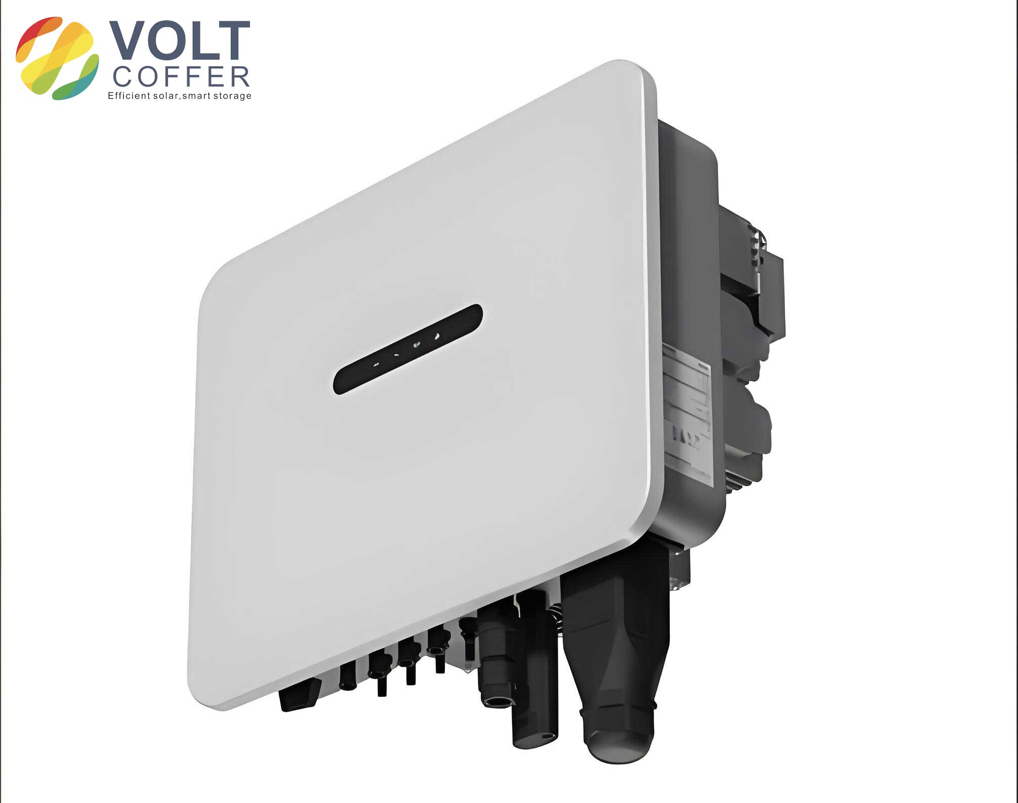
The topology of a typical two-stage PV on-grid inverter system is considered. The DC side, comprising the PV array and a DC-DC converter, is represented by a constant DC voltage source across a large capacitor \(C_{dc}\) for the purpose of analyzing the inverter control. The inverter is connected to the grid through an LCL filter (with inductances \(L_1\), \(L_2\) and capacitance \(C_f\)) and a grid impedance \(L_g\). The voltages at the PCC and the grid are denoted as \(v\) and \(v_g\), respectively.
Under normal balanced conditions, the primary goal of the on-grid inverter is to inject active power. However, during an asymmetrical fault, the PCC voltage contains both positive- and negative-sequence components (zero-sequence is neglected for wye-connected systems with isolated neutral). The instantaneous voltages in the stationary \(\alpha\beta\)-frame can be expressed as:
$$
\begin{bmatrix} v_{\alpha} \\ v_{\beta} \end{bmatrix} = \begin{bmatrix} v_{\alpha}^+ + v_{\alpha}^- \\ v_{\beta}^+ + v_{\beta}^- \end{bmatrix} = \begin{bmatrix} V^+ \sin(\omega t + \varphi^+) + V^- \sin(\omega t + \varphi^-) \\ -V^+ \cos(\omega t + \varphi^+) + V^- \cos(\omega t + \varphi^-) \end{bmatrix}
$$
where \(V^+\), \(V^-\) are the positive- and negative-sequence voltage magnitudes, and \(\varphi^+\), \(\varphi^-\) are their respective phase angles.
Conventional control strategies for on-grid inverters during faults often derive current references based on the instantaneous power theory. The instantaneous active and reactive power are given by:
$$
\begin{bmatrix} p \\ q \end{bmatrix} = \frac{3}{2} \begin{bmatrix} v_{\alpha} & v_{\beta} \\ v_{\beta} & -v_{\alpha} \end{bmatrix} \begin{bmatrix} i_{\alpha} \\ i_{\beta} \end{bmatrix}
$$
If the goal is to inject constant active and reactive power references \(P_{ref}\) and \(Q_{ref}\), the corresponding current references are:
$$
\begin{bmatrix} i_{\alpha, p}^{ref} \\ i_{\beta, p}^{ref} \end{bmatrix} = \frac{2P_{ref}}{3((V^+)^2 – (V^-)^2)} \begin{bmatrix} v_{\alpha} \\ v_{\beta} \end{bmatrix}, \quad \begin{bmatrix} i_{\alpha, q}^{ref} \\ i_{\beta, q}^{ref} \end{bmatrix} = \frac{2Q_{ref}}{3((V^+)^2 – (V^-)^2)} \begin{bmatrix} v_{\beta} \\ -v_{\alpha} \end{bmatrix}
$$
However, these references contain second-order harmonic components, leading to non-sinusoidal currents. To obtain sinusoidal currents, a notch filter can be applied to remove the double-frequency component from the voltage terms before calculating the references. While this yields sinusoidal current injection, the resulting instantaneous power \(p\) and \(q\) inevitably contain oscillatory components at twice the grid frequency, as shown by:
$$
p = P_{ref} – \frac{2P_{ref} V^+ V^-}{(V^+)^2 – (V^-)^2} \cos(2\omega t + \varphi^+ + \varphi^-)
$$
$$
q = Q_{ref} – \frac{2Q_{ref} V^+ V^-}{(V^+)^2 – (V^-)^2} \cos(2\omega t + \varphi^+ + \varphi^-)
$$
These power oscillations can stress the DC-link capacitor and negatively impact grid stability. This illustrates the inherent trade-off in traditional methods between obtaining sinusoidal currents and suppressing power oscillations. The proposed strategy for the on-grid inverter aims to resolve this conflict.
The core of the proposed method is a phase compensation technique applied to the measured PCC voltages. This is achieved by processing the \(\alpha\beta\)-voltages through a specific Band-Pass Filter (BPF). The key transformation is:
$$
\begin{bmatrix} v_{\alpha}’ \\ v_{\beta}’ \end{bmatrix} = \begin{bmatrix} -v_{\beta} \\ v_{\alpha} \end{bmatrix}
$$
This operation effectively introduces a phase shift. In the time domain, if the original voltage vector has components \(v_{\alpha} = V \sin(\omega t)\) and \(v_{\beta} = -V \cos(\omega t)\), the transformed vector becomes \(v_{\alpha}’ = V \cos(\omega t) = V \sin(\omega t + 90^\circ)\) and \(v_{\beta}’ = V \sin(\omega t) = -V \cos(\omega t + 90^\circ)\). This 90-degree shift, combined with the original vectors, is utilized to reformulate the power calculation. We define a modified instantaneous power calculation using the original and phase-shifted voltages:
$$
\begin{bmatrix} p \\ q \end{bmatrix} = \frac{3}{2} \begin{bmatrix} v_{\alpha} & v_{\beta} \\ v_{\beta}’ & -v_{\alpha}’ \end{bmatrix} \begin{bmatrix} i_{\alpha} \\ i_{\beta} \end{bmatrix}
$$
Solving for the current references that yield constant power injection \(P_{ref}\) and \(Q_{ref}\) gives:
$$
\begin{bmatrix} i_{\alpha}^{ref} \\ i_{\beta}^{ref} \end{bmatrix} = \frac{2}{3X} \begin{bmatrix} v_{\beta}’ & -v_{\beta} \\ -v_{\alpha}’ & v_{\alpha} \end{bmatrix} \begin{bmatrix} P_{ref} \\ Q_{ref} \end{bmatrix}
$$
where \(X = v_{\alpha} v_{\beta}’ – v_{\beta} v_{\alpha}’ = (V^+)^2 – (V^-)^2\). Substituting the expressions for \(v_{\alpha}, v_{\beta}, v_{\alpha}’, v_{\beta}’\) reveals a critical result: the calculated current references \(i_{\alpha}^{ref}\) and \(i_{\beta}^{ref}\) are purely sinusoidal at the fundamental frequency. More importantly, when these sinusoidal currents are injected, the resulting instantaneous active and reactive power are constant, devoid of any second-harmonic oscillation. This allows the on-grid inverter to simultaneously achieve sinusoidal current injection and elimination of both active and reactive power oscillations, a significant advantage over conventional strategies.
The primary objective during a fault is voltage support. Following common grid codes (e.g., the LVRT curve), the required reactive current reference \(I_{q}^{ref}\) is determined based on the depth of the voltage sag at the PCC. The positive-sequence voltage magnitude \(V^+\) is used to calculate the per-unit voltage dip. The reactive power reference is then:
$$
Q_{ref} =
\begin{cases}
0, & \text{if } V^+ \geq 0.9 \, p.u. \\
\frac{3}{2} S_N (0.9 – V^+), & \text{if } 0.2 \, p.u. < V^+ < 0.9 \, p.u. \\
1.05 \, S_N, & \text{if } V^+ \leq 0.2 \, p.u.
\end{cases}
$$
where \(S_N\) is the rated apparent power of the on-grid inverter. The corresponding reactive current components in the \(\alpha\beta\)-frame are derived as:
$$
\begin{bmatrix} i_{\alpha, q}^{ref} \\ i_{\beta, q}^{ref} \end{bmatrix} = \frac{2 Q_{ref}}{3((V^+)^2 – (V^-)^2)} \begin{bmatrix} v_{\beta}’ \\ -v_{\alpha}’ \end{bmatrix}
$$
A critical constraint for the safe operation of the on-grid inverter is that its output current must not exceed the maximum allowable current, typically \(I_{max} = 1.1 \times I_{rated}\). The initial reactive current reference calculated for voltage support may violate this limit. Therefore, a current limiting algorithm is essential. First, the magnitude of the three-phase reactive current \(I_{q, abc}^{max}\) is computed from the \(\alpha\beta\) references. The final limited reactive power reference is:
$$
Q_{ref}^{lim} = \min \left( Q_{ref}, \quad S_N \cdot \frac{I_{max}}{I_{q, abc}^{max}} \right)
$$
This ensures that the reactive current injection is prioritized for voltage support but curtailed if it risks exceeding the inverter’s current capability.
Once the current limit is respected for reactive injection, there may be remaining inverter capacity available. This capacity can be utilized to inject active power, enhancing the utilization of the on-grid inverter and providing additional support to the grid. The maximum available active power reference is determined by:
$$
P_{ref}^{lim} = \sqrt{ S_N^2 – (Q_{ref}^{lim})^2 }
$$
The final current references for the on-grid inverter are the sum of the limited reactive and active current components:
$$
\begin{bmatrix} i_{\alpha}^{ref} \\ i_{\beta}^{ref} \end{bmatrix} = \begin{bmatrix} i_{\alpha, q}^{ref, lim} \\ i_{\beta, q}^{ref, lim} \end{bmatrix} + \begin{bmatrix} i_{\alpha, p}^{ref, lim} \\ i_{\beta, p}^{ref, lim} \end{bmatrix}
$$
where the active current references \(i_{\alpha, p}^{ref, lim}, i_{\beta, p}^{ref, lim}\) are calculated using \(P_{ref}^{lim}\) in the phase-compensated reference current formula. This complete control strategy for the on-grid inverter integrates phase compensation for oscillation elimination, dynamic voltage support, strict current limiting, and maximum capacity utilization.
The performance of the proposed on-grid inverter control strategy is validated through detailed time-domain simulations in Matlab/Simulink. The system parameters are listed in Table 1.
| Parameter | Value | Unit |
|---|---|---|
| Rated Apparent Power, \(S_N\) | 100 | kVA |
| Grid Nominal Voltage (Phase), \(V_N\) | 311 | V |
| Grid Fundamental Frequency, \(f_0\) | 50 | Hz |
| DC-link Voltage, \(U_{dc}\) | 1000 | V |
| Inverter-side Inductor, \(L_1\) | 0.6 | mH |
| Grid-side Inductor, \(L_2\) | 7 | mH |
| Filter Capacitor, \(C_f\) | 110 | μF |
Two case studies are conducted. Case 1 examines a single-phase fault where Phase A voltage dips to 0.7 p.u. The proposed strategy is compared with a conventional notch-filter-based strategy. The results, summarized in Table 2, clearly demonstrate the superiority of the proposed method for the on-grid inverter. While both methods keep the current within limits, only the proposed phase-compensation strategy successfully elevates the minimum PCC phase voltage to the required 0.9 p.u. after the activation of maximum power injection. The conventional strategy fails to meet this grid code requirement because its current limiting constraint forces a reduction in active power output, whereas the phase relationship in the proposed method allows more effective voltage support with the same current magnitude.
| Metric | Conventional Strategy | Proposed Strategy |
|---|---|---|
| PCC Min Voltage (with max power) | < 0.9 p.u. (Requirement NOT met) | = 0.9 p.u. (Requirement MET) |
| Output Current | Within limit \(I_{max}\) | Within limit \(I_{max}\) |
| Active Power Oscillation | Present (\(2^{nd}\) harmonic) | Eliminated |
| Reactive Power Oscillation | Present (\(2^{nd}\) harmonic) | Eliminated |
Case 2 investigates a more complex asymmetrical fault with voltages: \(V_a=0.78\) p.u., \(V_b=0.75\) p.u., \(V_c=1.05\) p.u. The proposed on-grid inverter control is compared against a parameter-based strategy from the literature which selectively suppresses either active or reactive power oscillation. The performance is quantified in Table 3. The proposed strategy successfully eliminates both power oscillations (reducing them to near zero), whereas the compared strategy can only minimize one at the expense of increasing the other. Furthermore, the proposed method achieves better voltage support (bringing both faulted phase voltages above 0.9 p.u.) while injecting less total apparent power. This efficiency stems from the beneficial phase alignment of the injected active current in the proposed method, which also contributes positively to the PCC voltage support.
| Metric | Parameter-based Strategy | Proposed On-Grid Inverter Strategy |
|---|---|---|
| Active Power Oscillation Amplitude | 0.012 p.u. to 0.227 p.u. (Varies with param.) | ~0.01 p.u. (Eliminated) |
| Reactive Power Oscillation Amplitude | 0.013 p.u. to 0.171 p.u. (Varies with param.) | ~0.011 p.u. (Eliminated) |
| PCC Voltage Support (Phase A & B) | Below or marginally at 0.9 p.u. | Above 0.9 p.u. |
| Total Injected Apparent Power | Higher | Lower (More efficient support) |
In conclusion, this paper has presented a comprehensive and effective fault ride-through control strategy for on-grid inverters operating under asymmetrical grid faults. The proposed method, centered on a voltage phase compensation technique, successfully resolves the classical conflict between achieving sinusoidal current injection and eliminating power oscillations. It guarantees that the instantaneous active and reactive power outputs of the on-grid inverter are free from double-frequency ripples. Integrated with a dynamic voltage support mechanism based on grid codes, a rigorous current limiting algorithm, and a maximum capacity utilization module, the strategy ensures reliable and grid-supportive operation of the on-grid inverter. Simulation results confirm that the proposed control enables the on-grid inverter to meet stringent grid code requirements for voltage support, stay within safe current limits, and utilize its available capacity optimally, all while maintaining stable, oscillation-free power exchange. Future work will focus on enhancing the robustness of the phase compensation filter against grid frequency deviations, a key step towards the practical deployment of this advanced on-grid inverter control strategy.