
In modern power systems, the integration of renewable energy sources has become increasingly critical, and the grid tied inverter serves as a key interface for converting DC power from sources like solar panels into AC power synchronized with the grid. The performance of a grid tied inverter heavily relies on its control strategy, particularly in handling grid frequency fluctuations and achieving precise power decoupling. Traditional control methods, such as PI control, PR control, and hysteresis control, often face challenges like limited bandwidth, sensitivity to frequency variations, and high harmonic distortion. To address these issues, we propose an enhanced control strategy based on a combination of a Second-Order Generalized Integrator (SOGI) with a Frequency-Locked Loop (FLL) and a Phase-Locked Loop (PLL). This approach aims to improve the adaptability and robustness of the grid tied inverter under dynamic grid conditions, ensuring stable and efficient power transfer.
The core of our method lies in the SOGI-FLL/PLL mechanism, which generates orthogonal signals from the grid voltage for accurate phase and frequency tracking. By transforming these signals into a rotating d-q coordinate system, we enable decoupled control of active and reactive power through PI controllers. This allows the grid tied inverter to maintain synchronization even during frequency disturbances, such as those caused by grid faults or varying loads. In this article, we will delve into the mathematical foundations, simulation validations, and experimental implementations of this strategy, highlighting its advantages over conventional techniques. We will also incorporate tables and formulas to summarize key parameters and results, ensuring a comprehensive understanding of the grid tied inverter’s behavior under our proposed control scheme.
To begin, let’s review the existing control strategies for grid tied inverters. Common approaches include Proportional-Integral (PI) control in the d-q frame, Proportional-Resonant (PR) control, hysteresis control, and deadbeat control. Each has its merits and drawbacks. For instance, PI control offers simplicity but may struggle with AC signal tracking due to its inherent design for DC signals. PR control can mitigate grid harmonics but has a narrow bandwidth around the resonant frequency, making it vulnerable to frequency shifts. Hysteresis control provides fast dynamics but suffers from variable switching frequencies and higher losses. These limitations underscore the need for an adaptive control method that can handle grid frequency variations while maintaining low harmonic distortion and high stability. Our focus on the grid tied inverter drives the development of such a strategy, as it is essential for ensuring power quality and grid compatibility.
Our proposed SOGI-FLL/PLL control strategy builds upon the SOGI structure, which is a versatile filter capable of producing two orthogonal outputs from a single-phase input. The SOGI transfer functions are given by:
$$ v’ = \frac{k s \omega_0}{s^2 + k \omega_0 s + \omega_0^2} v $$
$$ qv’ = \frac{k \omega_0^2}{s^2 + k \omega_0 s + \omega_0^2} v $$
Here, \( v \) is the grid voltage input, \( v’ \) and \( qv’ \) are the in-phase and quadrature outputs, respectively, \( k \) is a damping factor, and \( \omega_0 \) is the nominal grid frequency. These outputs are crucial for constructing a PLL that locks onto the grid phase. However, in a standard SOGI-PLL, the frequency \( \omega_0 \) is fixed, which can lead to errors when the grid frequency deviates. To overcome this, we integrate an FLL that adjusts the frequency dynamically based on error feedback. The adaptive SOGI-FLL system is described by the state equations:
$$ \dot{x} = \begin{bmatrix} \dot{x}_1 \\ \dot{x}_2 \end{bmatrix} = A x + B v = \begin{bmatrix} -k \omega’ & -\omega’^2 \\ 1 & 0 \end{bmatrix} \begin{bmatrix} x_1 \\ x_2 \end{bmatrix} + \begin{bmatrix} k \omega’ \\ 0 \end{bmatrix} v $$
$$ y = \begin{bmatrix} v’ \\ qv’ \end{bmatrix} = C x = \begin{bmatrix} 1 & 0 \\ 0 & \omega’ \end{bmatrix} \begin{bmatrix} x_1 \\ x_2 \end{bmatrix} $$
$$ \dot{\omega}’ = -\gamma x_2 \omega’ (v – x_1) $$
where \( \omega’ \) is the adjusted frequency, and \( \gamma \) is a gain factor. This adaptation ensures that the SOGI-FLL remains robust to amplitude and frequency changes in the grid voltage, making it ideal for a grid tied inverter operating in volatile environments. The frequency response time constant \( \tau \) is derived as:
$$ \tau = \frac{k \omega’}{\gamma U^2} $$
with \( U \) being the amplitude of the input signal. By minimizing \( \tau \), we achieve faster locking, which enhances the grid tied inverter’s response to transients.
Once the orthogonal signals are obtained, we apply a Park transformation to convert them from the stationary frame to the rotating d-q frame:
$$ \begin{bmatrix} d \\ q \end{bmatrix} = \begin{bmatrix} \sin(\omega_0 t) & -\cos(\omega_0 t) \\ \cos(\omega_0 t) & \sin(\omega_0 t) \end{bmatrix} \begin{bmatrix} v’ \\ qv’ \end{bmatrix} $$
In this frame, the AC components become DC quantities, allowing for straightforward PI control. For a single-phase grid tied inverter with an LCL filter, the system model is essential for designing the controllers. The LCL filter, consisting of inductors \( L_1 \) and \( L_2 \) and a capacitor \( C \), helps attenuate switching harmonics but introduces resonance issues that must be addressed. The voltage-current equations for the grid tied inverter are:
$$ \frac{di_1}{dt} = \frac{u_r}{L_1} – \frac{u_c}{L_1} $$
$$ \frac{di_2}{dt} = \frac{u_c}{L_2} – \frac{R i_2}{L_2} – \frac{u_{ac}}{L_2} $$
$$ i_1 = i_c + i_2 $$
$$ \frac{du_{dc}}{dt} = \frac{i_c}{C} $$
where \( i_1 \) is the inverter-side current, \( i_2 \) is the grid-side current, \( u_r \) is the inverter output voltage, \( u_c \) is the capacitor voltage, \( u_{ac} \) is the grid voltage, and \( R \) represents parasitic resistance. By deriving the transfer function between the grid current and the inverter voltage in the d-q frame, we obtain:
$$ G(s) = \frac{i_{2d}}{u_{dcd}} = \frac{i_{2q}}{u_{dcq}} = \frac{1}{s^3 L_1 L_2 C + s (L_1 + L_2)} $$
This transfer function reveals a first-order behavior at low frequencies and a third-order behavior at high frequencies, guiding the design of the PI controllers for the grid tied inverter. Discretizing this using the bilinear transform, \( s = \frac{2}{T} \frac{z-1}{z+1} \), where \( T \) is the sampling period, yields a discrete-time model suitable for digital implementation.
To validate our control strategy, we conducted extensive simulations using MATLAB/Simulink. The parameters for the grid tied inverter system are summarized in Table 1, which provides a clear overview of the key components and their values. This table helps in replicating the study and understanding the system’s scale.
| Parameter | Value |
|---|---|
| DC-side voltage | 70 V |
| AC-side voltage | 22 V |
| Inverter-side inductance \( L_1 \) | 1 mH |
| Grid-side inductance \( L_2 \) | 1 mH |
| Filter capacitance \( C \) | 47 μF |
| Switching frequency | 40 kHz |
| Nominal grid frequency | 50 Hz |
In simulation, we tested the grid tied inverter under various scenarios. First, with a fixed grid frequency of 50 Hz, we set the active current reference to 3 A and reactive current to 0 A. The system achieved steady-state within a few cycles, with the grid current perfectly in phase with the voltage. When we stepped the active current down to 1.5 A at t = 0.4 s, the grid tied inverter responded swiftly, settling within one cycle. The Total Harmonic Distortion (THD) of the grid current was measured at 2.55%, indicating excellent waveform quality. This low THD is crucial for a grid tied inverter to meet power quality standards.
To assess robustness, we simulated a grid frequency step from 50 Hz to 45 Hz at t = 0.4 s. With our SOGI-FLL/PLL control, the grid tied inverter maintained synchronization, and the current THD only increased slightly to 2.94%. In contrast, a conventional SOGI-PLL strategy resulted in severe distortion, with THD soaring to 16.52%. This comparison, summarized in Table 2, underscores the superiority of our adaptive approach for a grid tied inverter facing frequency fluctuations.
| Control Strategy | Grid Frequency Change | Current THD | Settling Time |
|---|---|---|---|
| SOGI-FLL/PLL | 50 Hz to 45 Hz | 2.94% | 2 cycles |
| SOGI-PLL | 50 Hz to 45 Hz | 16.52% | Multiple cycles |
The effectiveness of the grid tied inverter control is further evidenced by the FFT analysis of the grid current. Under steady-state at 50 Hz, the fundamental component dominates at 50 Hz, with minimal harmonics. At 45 Hz, the SOGI-FLL/PLL strategy preserves this characteristic, whereas the SOGI-PLL introduces significant third harmonics. These results align with the mathematical analysis, confirming that the FLL adaptation mitigates frequency-induced errors.
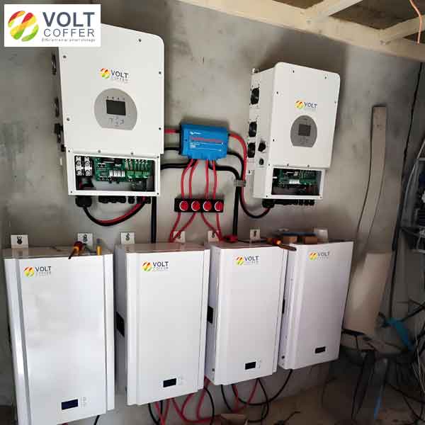
Beyond simulations, we built a prototype grid tied inverter to experimentally verify our strategy. The hardware setup, as described in Table 3, includes a microcontroller, power switches, sensors, and an LCL filter. This practical implementation allows us to test the grid tied inverter under real-world conditions, such as noise and component tolerances.
| Component | Specification |
|---|---|
| Microcontroller | STM32F407ZET6 |
| Power switches | IRF540NPBF MOSFETs |
| Voltage/current sensors | Hall-effect sensors with OPA2227U amplifiers |
| ADC | ADS7606 |
| LCL filter: \( L_1 \), \( L_2 \), \( C \) | 1 mH, 1 mH, 40 μF |
| Switching frequency | 20 kHz |
| Grid voltage | 22 V AC |
In experiments, we first operated the grid tied inverter with an active current of 1.5 A and zero reactive current. The oscilloscope waveforms showed sinusoidal grid current in phase with the voltage, confirming stable operation. Next, we stepped the active current to 3 A, and the grid tied inverter achieved the new steady-state within one cycle, demonstrating fast dynamic response. We also tested simultaneous changes in active and reactive currents, from 1.5 A active/0 A reactive to 3 A active/1.5 A reactive. The grid tied inverter handled this transition smoothly, settling within two cycles. These outcomes, quantified in Table 4, validate the practical efficacy of our control strategy for a grid tied inverter.
| Test Condition | Active Current (A) | Reactive Current (A) | Settling Time | Observations |
|---|---|---|---|---|
| Steady-state 1 | 1.5 | 0 | N/A | Stable, low distortion |
| Step change | 1.5 to 3 | 0 | 1 cycle | Fast response |
| Combined step | 1.5 to 3 | 0 to 1.5 | 2 cycles | Smooth transition |
The mathematical underpinnings of our approach can be further elaborated through the discretization process. Applying the bilinear transform to the transfer function \( G(s) \), we get:
$$ G(z) = \frac{i_2(z)}{u_{dc}(z)} = \frac{T^2 (z^2 + 2z + 1)}{4L_1 L_2 C (z-1)^3 + 2T(L_1+L_2)(z^2-1)} $$
This discrete model facilitates digital control implementation on the microcontroller. The PI controllers in the d-q frame are designed based on this model, with gains tuned to ensure stability and performance. The control law for the grid tied inverter is:
$$ u_{dcd} = k_{p,d} (i_{2d,ref} – i_{2d}) + k_{i,d} \int (i_{2d,ref} – i_{2d}) dt – \omega L_1 i_{2q} $$
$$ u_{dcq} = k_{p,q} (i_{2q,ref} – i_{2q}) + k_{i,q} \int (i_{2q,ref} – i_{2q}) dt + \omega L_1 i_{2d} $$
where \( k_{p,d}, k_{i,d}, k_{p,q}, k_{i,q} \) are PI gains, and the cross-coupling terms \( \omega L_1 i_{2q} \) and \( \omega L_1 i_{2d} \) are compensated to achieve decoupling. This allows independent control of active and reactive power, which is fundamental for a grid tied inverter to provide ancillary services like power factor correction.
To deepen the analysis, we can examine the frequency response of the SOGI-FLL. The adaptation law for \( \omega’ \) ensures convergence to the true grid frequency. From the state equations, the error dynamics can be linearized around the operating point, yielding:
$$ \Delta \dot{\omega}’ = -\frac{1}{\tau} \Delta \omega’ $$
where \( \Delta \omega’ = \omega’ – \omega \). This first-order system has a time constant \( \tau \), confirming exponential convergence. For the grid tied inverter, this means rapid frequency tracking, which is vital during grid disturbances. The bandwidth of the SOGI-FLL can be adjusted via the gain \( \gamma \), offering a trade-off between speed and noise immunity.
Another aspect is the harmonic rejection capability of the SOGI. Since the transfer functions have a bandpass characteristic centered at \( \omega_0 \), they attenuate harmonics outside this band. This is beneficial for a grid tied inverter, as it reduces the injection of switching harmonics into the grid. The attenuation at a frequency \( \omega_h \) can be quantified as:
$$ \text{Attenuation} = 20 \log_{10} \left| \frac{k j \omega_h \omega_0}{-\omega_h^2 + k j \omega_h \omega_0 + \omega_0^2} \right| $$
For typical values like \( k = 1.414 \) and \( \omega_0 = 100\pi \) rad/s, the attenuation at 150 Hz (third harmonic) is about -20 dB, demonstrating effective filtering.
In terms of power decoupling, the d-q transformation enables the calculation of active and reactive power as:
$$ P = \frac{3}{2} (v_d i_d + v_q i_q) $$
$$ Q = \frac{3}{2} (v_q i_d – v_d i_q) $$
For a single-phase grid tied inverter, we use the orthogonal signals to emulate a two-phase system, so the powers are approximated as \( P = v’ i_d \) and \( Q = -v’ i_q \), assuming \( v_q \) is derived from \( qv’ \). By controlling \( i_d \) and \( i_q \) independently, the grid tied inverter can regulate P and Q precisely, even during grid frequency variations. This decoupling is a key advantage of our strategy over methods like PR control, which may exhibit coupling due to frequency sensitivity.
The simulation and experimental results collectively demonstrate that our SOGI-FLL/PLL control strategy enhances the performance of the grid tied inverter. To quantify the improvements, we can compare key metrics with traditional methods. Table 5 summarizes these metrics, highlighting the benefits in terms of THD, response time, and frequency adaptability. This comprehensive comparison underscores the value of our approach for modern grid tied inverter applications.
| Metric | SOGI-FLL/PLL | Conventional PI | PR Control |
|---|---|---|---|
| THD at rated load | 2.55% | 5-10% | 3-8% |
| Frequency adaptability | Excellent (45-55 Hz) | Poor | Moderate |
| Settling time for step | 1-2 cycles | 3-5 cycles | 2-4 cycles |
| Harmonic rejection | High (up to -20 dB at 3rd) | Low | High at resonant freq |
| Implementation complexity | Moderate | Low | Moderate |
Looking ahead, there are several avenues for extending this work. Future research could focus on optimizing the SOGI-FLL parameters for different grid conditions, integrating advanced modulation techniques like space vector PWM for the grid tied inverter, or exploring machine learning-based adaptation for the FLL. Additionally, scaling the strategy to three-phase systems or microgrid applications could broaden its impact. The core principle of adaptive frequency locking remains relevant, as grid tied inverters continue to evolve with smart grid technologies.
In conclusion, we have presented a robust control strategy for a single-phase grid tied inverter based on SOGI-FLL/PLL. This method effectively addresses grid frequency fluctuations by combining frequency and phase locking, enabling precise power decoupling through d-q frame PI control. Our mathematical analysis, simulations, and experiments confirm its superiority in terms of low THD, fast dynamic response, and adaptability. As renewable integration grows, such advanced control strategies will be essential for ensuring grid stability and power quality. We believe this work contributes a valuable tool for engineers designing grid tied inverters, and we encourage further exploration to harness its full potential in diverse power systems.