
As an engineer specializing in photovoltaic (PV) systems, I have witnessed the rapid growth of renewable energy under the “dual carbon” strategy. Traditional fossil fuels are increasingly inadequate for societal needs, prompting a shift toward wind and solar power. Among these, PV power generation stands out due to its environmental benefits, renewability, safety, reliability, and low maintenance costs. In PV power stations, the grid-tied inverter is a critical component, serving as the bridge between solar arrays and the electrical grid. Its proper application and maintenance are essential for enhancing energy conversion efficiency, ensuring grid stability, and addressing energy and environmental challenges. In this article, I will delve into the application of grid-tied inverters in PV stations, supported by detailed analyses, tables, and formulas, and propose comprehensive maintenance measures to improve operational reliability and economic performance.
The grid-tied inverter is a specialized device that converts direct current (DC) generated by PV arrays into alternating current (AC) synchronized with the grid. Its operation relies on the photovoltaic effect, where solar cells produce DC electricity, which is then inverted to AC for grid integration. The core components typically include an inverter bridge, filters, transformers, and control circuits. To understand its functionality, consider the basic principle: a grid-tied inverter adjusts voltage and frequency to match grid standards, enabling seamless power injection. The conversion process can be summarized by the power balance equation, where the input DC power \(P_{dc}\) is transformed to output AC power \(P_{ac}\) with efficiency \(\eta\):
$$ P_{ac} = \eta \cdot P_{dc} $$
Efficiency \(\eta\) is a key metric, often exceeding 98% in modern grid-tied inverters, highlighting their role in minimizing energy losses. The inverter’s control system employs techniques like Maximum Power Point Tracking (MPPT) to optimize energy harvest from PV arrays under varying environmental conditions. MPPT algorithms adjust the operating voltage to maximize power output, expressed as:
$$ P_{max} = V_{mpp} \times I_{mpp} $$
where \(V_{mpp}\) and \(I_{mpp}\) are the voltage and current at the maximum power point. This dynamic adjustment is crucial for maintaining high performance in PV stations.
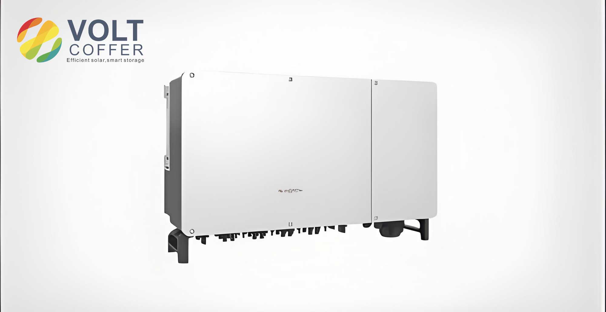
Grid-tied inverters come in various types, each suited for different PV station scales and configurations. Based on my experience, the primary categories are centralized, string, and micro inverters. Each type has distinct advantages and limitations, influencing their application in PV stations. Below is a comparative table summarizing their characteristics:
| Type | Power Range | Key Features | Typical Applications | Cost (per watt) |
|---|---|---|---|---|
| Centralized Inverter | 500 kW to MW+ | High power output, cost-effective, single MPPT | Large-scale PV plants | $0.3 – $0.4 |
| String Inverter | 1 kW to 60 kW | Multiple MPPTs, flexible configuration, better shade tolerance | Commercial and utility-scale systems | $0.5 – $0.7 |
| Micro Inverter | 0.2 kW to 1 kW | Module-level optimization, high reliability, plug-and-play | Residential and small commercial systems | $0.8 – $1.2 |
Centralized inverters, often used in megawatt-scale stations, aggregate DC power from multiple PV strings before inversion. Their operation involves high DC voltages, typically around 1000 V, which reduces transmission losses. The power conversion process can be modeled using a simplified circuit where the DC input voltage \(V_{dc}\) is inverted to AC voltage \(V_{ac}\) through pulse-width modulation (PWM). The output voltage waveform is given by:
$$ V_{ac}(t) = V_{dc} \cdot M \cdot \sin(2\pi f t) $$
where \(M\) is the modulation index and \(f\) is the grid frequency (e.g., 50 Hz or 60 Hz). However, centralized inverters may suffer from efficiency drops due to string mismatches or partial shading, as they rely on a single MPPT. In contrast, string inverters, which I commonly deploy in medium-sized stations, allow for independent MPPT per string, enhancing energy yield. Their output power \(P_{out}\) for a string with \(N\) modules can be expressed as:
$$ P_{out} = \sum_{i=1}^{N} \eta_i \cdot P_{module,i} $$
where \(\eta_i\) is the efficiency per string and \(P_{module,i}\) is the power of each module. Micro inverters, attached to individual PV modules, offer the highest granularity but at a higher cost. They excel in scenarios with complex shading or varying orientations, as each module operates independently, mitigating mismatch losses.
In practical applications within PV stations, the grid-tied inverter undergoes several operational states: startup, grid-connected generation, standby, shutdown, inspection, and fault handling. As an operator, I follow a systematic process to ensure smooth functioning. Firstly, during startup, the grid-tied inverter transitions from shutdown to grid-ready mode. This requires the PV array voltage to reach a threshold, typically above 520 V for many systems. The startup sequence involves charging DC capacitors and synchronizing with the grid voltage and frequency. The synchronization condition is critical:
$$ V_{grid} = V_{inverter}, \quad f_{grid} = f_{inverter}, \quad \phi_{grid} = \phi_{inverter} $$
where \(\phi\) denotes phase angle. Once synchronized, the grid-tied inverter closes its contactor to connect to the grid. Secondly, in grid-connected generation, the grid-tied inverter continuously converts DC to AC while performing MPPT. The power output fluctuates with solar irradiance \(G\) and temperature \(T\), modeled by:
$$ P_{dc} = G \cdot A \cdot \eta_{pv} \cdot [1 – \beta (T – T_{ref})] $$
where \(A\) is the array area, \(\eta_{pv}\) is PV module efficiency, \(\beta\) is the temperature coefficient, and \(T_{ref}\) is reference temperature. The grid-tied inverter adjusts its operation to maintain power quality, including harmonic distortion limits as per standards like IEEE 1547. Total harmonic distortion (THD) for current should be below 5%, calculated as:
$$ THD_i = \frac{\sqrt{\sum_{h=2}^{50} I_h^2}}{I_1} \times 100\% $$
where \(I_h\) is the harmonic current and \(I_1\) is the fundamental current. Thirdly, during standby mode, the grid-tied inverter monitors array voltage; if it drops below a setpoint (e.g., 480 V) for over 5 minutes, the inverter disconnects and enters standby, periodically checking for sufficient energy to resume. Fourthly, shutdown can be manual or automatic based on low irradiance or faults. The shutdown voltage \(V_{shutdown}\) is often set at 80% of the startup voltage. Fifthly, inspection involves routine checks of the grid-tied inverter’s indicators, cables, and cooling systems. I use a checklist that includes visual inspections for dust, damage, and thermal imaging to detect hotspots. Lastly, fault handling is triggered by alarms; common faults include over-temperature, grid faults, or communication errors. The grid-tied inverter may attempt auto-recovery after a delay, but persistent issues require manual intervention.
To elaborate on fault scenarios, I have encountered various issues with grid-tied inverters in PV stations. For instance, insulation resistance faults occur when DC leakage current exceeds safety limits, often due to moisture or degradation. The insulation resistance \(R_{ins}\) must be above 1 MΩ, measured using:
$$ R_{ins} = \frac{V_{dc}}{I_{leakage}} $$
Another common fault is grid overvoltage, where the grid-tied inverter disconnects if voltage exceeds 110% of nominal. This protects equipment but reduces energy yield. In such cases, I coordinate with grid operators to adjust tap changers or implement voltage regulation. Communication failures, often from RS485 link issues, require checking cable connections and protocol settings. The grid-tied inverter’s firmware logs error codes, which I analyze to pinpoint causes. For example, error “E08” might indicate DC overvoltage, prompting inspection of PV string configurations. By maintaining detailed records, I can identify patterns and preempt failures.
Maintenance of grid-tied inverters is paramount for long-term reliability. I categorize maintenance into routine, preventive, and corrective measures. Routine maintenance, performed weekly or monthly, includes visual inspections and cleaning. Key tasks are summarized in the table below:
| Maintenance Activity | Frequency | Procedure | Tools Required |
|---|---|---|---|
| External Cleaning | Monthly | Remove dust from vents and enclosures using compressed air | Air compressor, brush |
| Cable Inspection | Quarterly | Check for abrasion, looseness, or corrosion in DC/AC cables | Thermal camera, multimeter |
| Terminal Tightening | Biannually | Torque check on electrical connections per manufacturer specs | Torque wrench, screwdriver |
| Fan and Cooling Check | Quarterly | Ensure fans operate smoothly; clean filters and heat sinks | Vacuum, lubricant |
| Parameter Verification | Monthly | Review inverter settings via HMI or software for deviations | Laptop, communication cable |
Preventive maintenance, conducted every three months, involves more thorough checks. I focus on the grid-tied inverter’s internal components, such as capacitors and IGBTs. Electrolytic capacitors degrade over time, with lifespan estimated by:
$$ L = L_0 \cdot 2^{\frac{T_0 – T}{10}} $$
where \(L_0\) is the rated lifetime at temperature \(T_0\), and \(T\) is operating temperature. In hot climates, I schedule capacitor replacement every 5-7 years to avoid failures. Additionally, I perform firmware updates to enhance MPPT algorithms and grid compliance. Preventive maintenance also includes testing protection functions, like anti-islanding, which ensures the grid-tied inverter shuts down during grid outages. The test involves simulating a grid failure and verifying disconnect time \(t_d\) meets standards (e.g., \(t_d < 2\) seconds).
Corrective maintenance addresses faults after they occur. When a grid-tied inverter trips, I follow a systematic approach: first, isolate the inverter by opening DC and AC switches; wait 5 minutes for capacitors to discharge; then diagnose using error codes and measurements. For instance, if IGBT overheating is indicated, I check cooling fans and ambient temperature. The junction temperature \(T_j\) can be estimated from case temperature \(T_c\) and power loss \(P_{loss}\):
$$ T_j = T_c + R_{th,jc} \cdot P_{loss} $$
where \(R_{th,jc}\) is the thermal resistance. If \(T_j\) exceeds 150°C, I replace the IGBT module. For communication issues, I inspect RS485 wiring and termination resistors, ensuring impedance matches (typically 120 Ω). After repairs, I conduct a performance test, measuring efficiency at different load points to confirm the grid-tied inverter operates within specs. Efficiency \(\eta\) is calculated as:
$$ \eta = \frac{P_{ac}}{P_{dc}} \times 100\% $$
where \(P_{ac}\) and \(P_{dc}\) are measured with power analyzers. I document all actions in a maintenance log, tracking mean time between failures (MTBF) to assess reliability.
Beyond basic maintenance, advanced strategies can optimize grid-tied inverter performance. In large PV stations, I implement condition monitoring systems that use sensors to track parameters like vibration, humidity, and output harmonics. Data analytics help predict failures; for example, increasing THD may indicate capacitor aging. I also emphasize environmental considerations, such as installing grid-tied inverters in well-ventilated areas to reduce thermal stress. The derating factor due to temperature is given by:
$$ P_{rated} = P_{nominal} \cdot [1 – k (T_{ambient} – T_{rated})] $$
where \(k\) is the derating coefficient (e.g., 0.5%/°C). Moreover, grid support functions, like reactive power control, are increasingly important. Modern grid-tied inverters can provide voltage regulation by injecting or absorbing reactive power \(Q\), related to active power \(P\) and power factor \(pf\):
$$ Q = P \cdot \tan(\cos^{-1}(pf)) $$
By setting appropriate power factor setpoints, I help stabilize the grid, especially in regions with high PV penetration. This aligns with grid codes that require grid-tied inverters to participate in frequency and voltage control.
In terms of application, the grid-tied inverter’s role extends beyond mere conversion. It enables grid integration of distributed PV resources, contributing to energy resilience. For instance, during peak demand, PV stations with grid-tied inverters can reduce grid load, lowering transmission losses. The power loss in lines \(P_{loss}\) is proportional to current squared:
$$ P_{loss} = I^2 \cdot R $$
where \(R\) is line resistance. By generating locally, PV stations mitigate these losses. Furthermore, grid-tied inverters facilitate smart grid interactions through communication protocols like Modbus or IEEE 2030.5. I often configure grid-tied inverters for remote monitoring, allowing real-time adjustment of output based on grid conditions. This demand response capability is crucial for balancing variable renewable generation.
To illustrate the economic impact, proper application and maintenance of grid-tied inverters directly affect the levelized cost of energy (LCOE). LCOE is calculated as:
$$ LCOE = \frac{C_{capex} + \sum_{t=1}^{n} \frac{C_{opex,t}}{(1+r)^t}}{\sum_{t=1}^{n} \frac{E_t}{(1+r)^t}} $$
where \(C_{capex}\) is capital expenditure, \(C_{opex,t}\) is annual operational cost (including maintenance), \(E_t\) is energy production, \(r\) is discount rate, and \(n\) is lifespan. By extending the grid-tied inverter’s lifespan through maintenance, I reduce \(C_{opex}\) and improve \(E_t\), lowering LCOE. Studies show that proactive maintenance can boost annual energy yield by 2-5%, significant for large stations.
In conclusion, the grid-tied inverter is indispensable in PV stations, converting solar energy efficiently and supporting grid stability. Its application involves careful selection based on station scale, followed by disciplined operational management. From my experience, a robust maintenance regimen—encompassing routine, preventive, and corrective actions—is key to maximizing uptime and performance. By leveraging monitoring technologies and adhering to best practices, we can enhance the reliability of grid-tied inverters, contributing to a sustainable energy future. As PV technology evolves, grid-tied inverters will continue to play a central role in integrating renewables, and ongoing innovation in their design and maintenance will further optimize PV station outcomes.