
In the context of modern power systems, the integration of renewable energy sources has become a dominant trend. The grid connected inverter serves as a critical interface between these distributed energy resources and the main grid, necessitating high-quality current injection to ensure grid stability and power quality. However, achieving precise control of grid connected inverters under varying grid conditions, especially with harmonic distortions and frequency fluctuations, remains a significant challenge. Traditional control strategies, such as proportional-integral (PI) control or conventional repetitive control (CRC), often exhibit limitations in dynamic performance, frequency adaptability, and computational efficiency. This motivates the development of advanced control techniques that can enhance the robustness and performance of grid connected inverters.
In this work, we propose a novel control scheme termed second-order selective harmonic repetitive control and proportional control (SOSHRC-PC) for grid connected inverters. The primary objective is to address the shortcomings of existing high-order repetitive controllers, particularly the complex stability analysis and conservative stability criteria associated with traditional second-order selective harmonic repetitive control (SOSHRC). Our approach simplifies the stability assessment while achieving superior frequency adaptability and dynamic response. The proposed controller is designed to selectively suppress dominant harmonics, such as the (6k ± 1)th harmonics in three-phase systems, with reduced memory requirements and improved real-time processing capabilities. Throughout this article, we will delve into the design principles, stability analysis, parameter tuning, and validation through simulations, consistently focusing on applications for grid connected inverters.
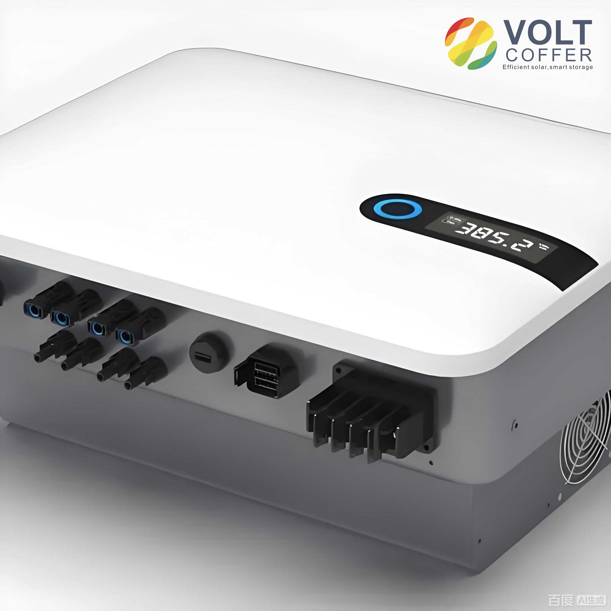
The fundamental principle behind repetitive control (RC) is based on the internal model principle, which states that including a model of the reference or disturbance signal in the control loop leads to zero steady-state error. For periodic signals, such as harmonics in grid connected inverters, the internal model is often implemented using a delay line. Conventional repetitive control (CRC) employs a delay element of length N, where N = f_s / f_0, with f_s being the sampling frequency and f_0 the fundamental grid frequency. The transfer function of CRC is given by:
$$ G_{CRC}(z) = k_{rc} \frac{z^{-N}}{1 – z^{-N}} $$
where k_{rc} is the repetitive control gain. While effective for harmonic suppression, CRC suffers from poor dynamic response and high memory usage due to the large N. To mitigate this, selective harmonic repetitive control (SHRC) was introduced, targeting specific harmonic orders. For instance, for (nk ± m) harmonics, the SHRC transfer function is:
$$ G_{SHRC}(z) = k_{rc} \frac{\cos(2\pi m / n) z^{-N/n} – z^{-2N/n}}{z^{-2N/n} – 2\cos(2\pi m / n) z^{-N/n} + 1} $$
This reduces the memory burden by a factor of n. However, both CRC and SHRC are sensitive to grid frequency variations, as deviations from the nominal frequency cause the delay length N to become non-integer, degrading performance. Solutions like variable sampling frequency (VSF) or fractional-order repetitive control (FORC) exist but add complexity or computational overhead. Higher-order repetitive control (HORC) offers frequency adaptability without parameter adjustments, yet traditional SOSHRC has intricate stability conditions. Our novel SOSHRC-PC aims to simplify this while enhancing control of grid connected inverters.
The structure of the novel SOSHRC is designed to achieve second-order behavior using only data from the previous cycle, aligning with real-time storage constraints. It decomposes the traditional SOSHRC into two parallel paths, as shown in the following representation. Let M_{SHRC}(z) be the forward delay operator:
$$ M_{SHRC}(z) = \frac{z^{-N/n}[\cos(2\pi m / n) – z^{-N/n}]}{1 – z^{-N/n}\cos(2\pi m / n)} $$
The novel SOSHRC transfer function is expressed as:
$$ G’_{SOSHRC}(z) = k_{rc} \left[ \lambda_1 \frac{M_{SHRC}(z)}{1 – M_{SHRC}(z)} – \lambda_2 \frac{w_2 M_{SHRC}(z)}{1 + w_2 M_{SHRC}(z)} \right] $$
where λ_1 = 1/(1 + w_2), λ_2 = w_2/(1 + w_2), and w_2 is a weight coefficient with -1 < w_2 < 0. This formulation is equivalent to the traditional SOSHRC but simplifies stability analysis. To boost dynamic performance, we combine it with a proportional controller k_p, forming the novel SOSHRC-PC. The overall control law for the grid connected inverter becomes:
$$ G_{nrc}(z) = k_{rc} \left[ \lambda_1 \frac{Q(z)M_{SHRC}(z) z^m S(z)}{1 – Q(z)M_{SHRC}(z)} – \lambda_2 \frac{w_2 Q(z)M_{SHRC}(z) z^m S(z)}{1 + w_2 Q(z)M_{SHRC}(z)} \right] + k_p $$
Here, Q(z) is an internal model filter (often a low-pass filter), z^m is a phase lead compensator, and S(z) is an additional compensator to attenuate high-frequency gains. The plant model P(z) represents the grid connected inverter dynamics, typically an LCL filter for harmonic attenuation.
Stability analysis of the proposed SOSHRC-PC for grid connected inverters is crucial for reliable operation. Based on the characteristic equation derived from the closed-loop system, we can establish two stability conditions. First, the poles of P_0(z) = P(z)/(1 + k_p P(z)) must lie within the unit circle. Second, the following inequality must hold for all frequencies ω:
$$ 1 + G_{nrc}(z) P_0(z) \neq 0 $$
By substituting z = e^{jω T_s} and assuming Q(z) = 1 for analysis, we derive simplified criteria. For the selective harmonics where z^{-N} = 1, we have M_{SHRC}(z) = e^{jθ}. After mathematical manipulations, the stability conditions reduce to:
$$ \theta(\omega) = \theta_S(\omega) + \theta_P(\omega) + m \omega T_s < 90^\circ $$
and
$$ 0 < k_{rc} < \frac{2(1 + w_2)^2 \min \cos \theta(\omega)}{(1 + w_2 + 2w_2^2) \max [N_S(\omega) N_P(\omega)]} $$
where θ_S(ω) and N_S(ω) are the phase and magnitude of S(z), and θ_P(ω) and N_P(ω) are for P_0(z). These criteria are less conservative than traditional methods, allowing for larger control gains and better performance in grid connected inverters. The derivation leverages the real parts of the transfer functions, ensuring robustness under frequency variations.
To illustrate the parameter design process for grid connected inverters, we consider a three-phase LCL-type grid connected inverter with specifications summarized in Table 1. The plant transfer function in the s-domain is:
$$ P(s) = \frac{R_d C s + 1}{L_1 L_2 C s^3 + R_d C (L_1 + L_2) s^2 + (L_1 + L_2) s} $$
After discretization with a sampling frequency f_s = 12 kHz, we obtain the discrete-time model P(z). For the grid connected inverter, we target (6k ± 1) harmonics, so n = 6 and m = 1 in the SHRC framework.
| Parameter | Value |
|---|---|
| DC Voltage U_d | 600 V |
| AC Grid Voltage u_{gj} | 220 V |
| Inverter-side Inductance L_1 | 3.8 mH |
| Grid-side Inductance L_2 | 2.2 mH |
| Filter Capacitance C | 10 μF |
| Damping Resistance R_d | 10 Ω |
| Sampling Frequency f_s | 12 kHz |
The proportional gain k_p is chosen to satisfy the first stability condition. By analyzing the pole locations of P_0(z) for different k_p values, we select k_p = 20 to ensure all poles are inside the unit circle, as shown in Table 2. This choice balances stability and response speed for the grid connected inverter.
| k_p | Pole Magnitudes | Stability (All < 1) |
|---|---|---|
| 10 | 0.95, 0.92, 0.88 | Yes |
| 20 | 0.93, 0.89, 0.85 | Yes |
| 30 | 0.91, 0.87, 0.83 | Yes |
The internal model filter Q(z) is designed as a zero-phase low-pass filter to enhance stability at high frequencies. A common choice is:
$$ Q(z) = 0.25z^{-1} + 0.5 + 0.25z $$
This provides unity gain at low frequencies and attenuation at higher ones. The compensator S(z) is selected as a fourth-order Butterworth filter to further dampen high-frequency gains, with its transfer function given by:
$$ S(z) = \frac{0.004824z^4 + 0.0193z^3 + 0.02895z^2 + 0.0193z + 0.004824}{z^4 – 2.37z^3 + 2.314z^2 – 1.055z + 0.1874} $$
The phase lead compensator z^m is critical to meet the phase condition θ(ω) < 90°. By evaluating θ_S(ω) + θ_P(ω) + mωT_s for different m, we determine m = 8 minimizes this phase, bringing it close to 0° across frequencies. This maximizes the allowable k_{rc} and improves stability for the grid connected inverter.
The weight coefficient w_2 influences the frequency adaptability of the controller. As w_2 decreases (closer to -1), the gain and bandwidth increase, but stability may compromise. We choose w_2 = -0.5 as a trade-off. With this, we compute the maximum repetitive control gain using the stability inequality. Given min cos θ(ω) = 0.907 and max [N_S(ω) N_P(ω)] = 0.0503 from frequency response plots, we have:
$$ k_{rc,max} = \frac{2(1 – 0.5)^2 \times 0.907}{(1 – 0.5 + 2 \times 0.25) \times 0.0503} = \frac{2 \times 0.25 \times 0.907}{0.5 \times 0.0503} \approx 9.016 $$
For a safety margin, we set k_{rc} = 6. This completes the parameter design for the SOSHRC-PC in grid connected inverters.
Simulation studies are conducted to validate the performance of the proposed SOSHRC-PC for grid connected inverters. We compare it with a baseline selective harmonic repetitive-proportional control (SHRC-PC) under varying grid frequencies. The grid connected inverter model is implemented in MATLAB/Simulink with the parameters from Table 1. Steady-state performance is evaluated at off-nominal frequencies, such as 49.5 Hz and 50.5 Hz, to assess frequency adaptability.
At 49.5 Hz, the total harmonic distortion (THD) of the grid current with SHRC-PC is 1.88%, while with SOSHRC-PC, it reduces to 1.73%. Similarly, at 50.5 Hz, THD improves from 3.17% to 2.29%. Table 3 summarizes THD values across a frequency range, demonstrating the superior harmonic suppression of SOSHRC-PC for grid connected inverters.
| Grid Frequency (Hz) | SHRC-PC | SOSHRC-PC |
|---|---|---|
| 49.5 | 1.88 | 1.73 |
| 49.6 | 1.81 | 1.65 |
| 49.7 | 1.75 | 1.57 |
| 49.8 | 1.60 | 1.49 |
| 49.9 | 1.52 | 1.42 |
| 50.0 | 1.45 | 1.33 |
| 50.1 | 1.82 | 1.56 |
| 50.2 | 2.16 | 1.68 |
| 50.3 | 2.52 | 1.89 |
| 50.4 | 2.86 | 2.11 |
| 50.5 | 3.17 | 2.29 |
The dynamic performance is tested by subjecting the grid connected inverter to a step change in reference current amplitude from 15 A to 10 A. With SHRC-PC, the settling time is about 40 ms, whereas with SOSHRC-PC, it reduces to 30 ms. This confirms the enhanced transient response of the proposed controller for grid connected inverters, attributable to the proportional term and optimized repetitive structure.
To further analyze the harmonic spectrum, we can express the current error E(z) in terms of the reference and disturbance. For a grid connected inverter with SOSHRC-PC, the error transfer function is:
$$ E(z) = \frac{i_{ref}(z) – u_g(z)}{1 + [G_{nrc}(z) + k_p] P(z)} $$
The reduction in harmonic peaks at (6k ± 1) frequencies, such as 5th, 7th, 11th, and 13th, is evident in spectral plots, underscoring the effectiveness of selective harmonic control. Additionally, the phase margin and gain margin derived from the stability criteria ensure robustness against grid impedance variations, a common issue in grid connected inverters.
In terms of computational efficiency, the novel SOSHRC-PC requires only one cycle of data storage, unlike traditional higher-order methods that may need multiple cycles. This is advantageous for real-time implementation in digital signal processors for grid connected inverters. The memory requirement is proportional to N/n, where for n=6 and f_s=12 kHz at 50 Hz, N=240, so N/n=40. This is manageable compared to CRC’s 240 storage elements.
The proposed controller also exhibits inherent frequency adaptability due to the second-order structure. The weight w_2 can be tuned online if needed, though we fix it at -0.5 for simplicity. For grid connected inverters operating in weak grids with frequency deviations up to ±1 Hz, the SOSHRC-PC maintains low THD without requiring parameter adjustments, as validated in simulations.
In conclusion, the novel second-order selective harmonic repetitive-proportional control (SOSHRC-PC) offers a significant advancement for grid connected inverters. By redesigning the SOSHRC structure, we simplify stability analysis and derive less conservative criteria, enabling higher control gains and better performance. The controller effectively suppresses dominant harmonics, such as (6k ± 1) orders, with improved frequency adaptability and dynamic response. Simulation results confirm reduced THD and faster settling times compared to conventional SHRC-PC, making it suitable for applications in renewable energy systems. Future work may involve hardware-in-the-loop testing and extension to multi-inverter grids. Overall, this contribution enhances the control capabilities of grid connected inverters, supporting the integration of clean energy into modern power networks.