
The integration of renewable energy sources like wind and solar photovoltaics has fundamentally transformed power systems from centralized generation to distributed paradigms. At the heart of this transition lies the grid connected inverter, the critical power electronic interface that converts DC power from sources or storage into AC power synchronized with the utility grid. As the penetration of these inverters rises, the grid itself exhibits characteristics of a “weak grid” – a system with non-negligible impedance leading to voltage imbalances, frequency fluctuations, and background harmonic distortion. These conditions impose stringent demands on the control system of a grid connected inverter, challenging its ability to inject high-quality current with low total harmonic distortion (THD) while maintaining robust stability under dynamic grid conditions.
High-gain current controllers are essential for meeting strict grid codes and power quality standards. Among them, the Repetitive Controller (RC) has gained widespread adoption in applications like uninterruptible power supplies, active power filters, and renewable energy systems due to its inherent ability to provide infinite gain at specific harmonic frequencies, theoretically eliminating periodic tracking errors. The conventional repetitive controller (CRC) employs an internal model based on a periodic delay line. Its transfer function in the discrete z-domain is often represented as:
$$G_{CRC}(z) = k_{rc} \frac{z^{-N}}{1 – z^{-N}}$$
where $k_{rc}$ is the control gain, and $N = f_s / f_g$ is the number of samples per fundamental period ($f_s$ is the sampling frequency, $f_g$ is the grid fundamental frequency). This structure places poles at $z = e^{j2\pi k/N}$ for $k=0,1,…,N-1$, corresponding to the DC component and all harmonic frequencies up to the Nyquist rate, enabling perfect tracking or rejection of any periodic signal with period $N$. However, this strength is also its critical weakness. The performance of a CRC is highly sensitive to the accuracy of the period $N$. In practical grid connected inverter applications, the grid frequency $f_g$ is not constant. Even slight deviations, common in weak or islanded grids, cause a mismatch between the controller’s internal resonant frequencies and the actual harmonic components of the grid signal. This mismatch drastically reduces the controller’s gain at the intended harmonic frequencies, leading to increased steady-state error, degraded harmonic suppression, and potential instability.
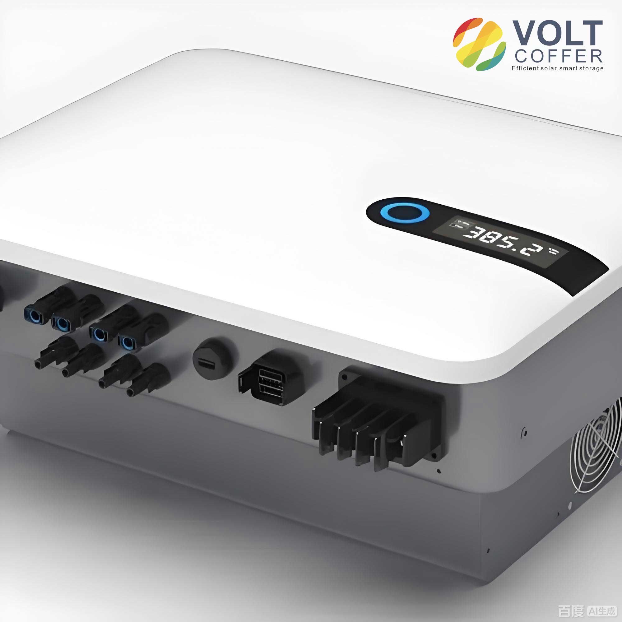
Several advanced RC schemes have been proposed to address this frequency adaptability issue. Fractional-order RC adjusts the delay length to a non-integer value to match a fractional period, but requires complex online computation of approximation filters. Virtual variable sampling frequency methods dynamically adjust the controller’s sampling rate, demanding specialized hardware capabilities. Another promising direction is High-Order Repetitive Control (HO-RC). By cascading multiple internal model blocks with specific weighting, HO-RC can widen the gain peak around harmonic frequencies, thereby improving robustness against frequency variations. A generalized form, the High-Order Selective Harmonic Repetitive Controller (HO-SHRC), focuses gain enhancement only on dominant harmonic families (e.g., $6k \pm 1$ harmonics in three-phase systems), offering improved dynamic response and reduced memory usage compared to full-spectrum HO-RC. The transfer function for an L-th order HO-SHRC can be expressed as:
$$G_{HO-SHRC}(z) = k_{rc} \frac{\sum_{l=1}^{L} w_l [M_{SHRC}(z)]^l}{1 – \sum_{l=1}^{L} w_l [M_{SHRC}(z)]^l}$$
where $M_{SHRC}(z)$ is the selective harmonic internal model. For targeting harmonics of order $nk \pm m$, it is given by:
$$M_{SHRC}(z) = \frac{z^{-N/n} – \cos(2\pi m/n)z^{-2N/n}}{1 – \cos(2\pi m/n)z^{-N/n}}$$
While effective, a fundamental limitation of HO-SHRC is that increasing the order $L$ to achieve higher robustness linearly increases the total delay in the control loop and the required memory for storing past error and output data. For $L=2$, the effective delay is $2N/n$; for $L=3$, it becomes $3N/n$, and so on. This growing delay impairs the system’s transient response and phase margin. Furthermore, the escalating memory requirement increases hardware cost and complexity, making very high-order ($L > 3$) implementations impractical, thus capping the achievable frequency adaptability. This creates a critical trade-off: higher order for better robustness versus lower order for better dynamics and lower cost.
This paper proposes a novel control strategy that breaks this trade-off: the Simplified Infinite-Order Selective Harmonic Repetitive Controller (SIO-SHRC). The core innovation is to use a geometric series weighting principle to approximate the behavior of an *infinite*-order HO-SHRC using a compact, computationally efficient structure equivalent to only a *second-order* controller. This approach delivers the high gain and superior frequency adaptability associated with a theoretically infinite memory of past cycles, while maintaining the low latency and minimal memory footprint of a simple second-order system. We present the complete theoretical derivation, a practical digital implementation structure requiring data from only one previous cycle, and a comprehensive stability analysis. Experimental results on a three-phase grid connected inverter prototype demonstrate that the proposed SIO-SHRC outperforms conventional CRC, SHRC, and HO-SHRC in terms of steady-state precision, harmonic suppression under frequency variations, dynamic response to step changes, and robustness to voltage sags.
Conceptual Foundation: From High-Order to Infinite-Order Approximation
The genesis of the SIO-SHRC lies in re-imagining the high-order structure. Consider the general form of an L-th order RC from Equation (2). If we extend this concept to an infinite order ($L \to \infty$) and separate the weighting coefficients for the numerator and denominator into two distinct geometric sequences, we obtain a conceptual infinite-order controller:
$$G_{\infty}(z) = \frac{\sum_{j=1}^{\infty} q_j [M(z)]^j}{1 – \sum_{j=1}^{\infty} k_j [M(z)]^j}$$
where $M(z)$ represents the core internal model (e.g., $M_{SHRC}(z)$), and $q_j$, $k_j$ are weighting sequences. Direct implementation is impossible. The key simplification is to choose these weights as terms of geometric progressions. Let:
$$q_j = q_1 \alpha^{j-1}, \quad k_j = k_1 \beta^{j-1}, \quad j=1,2,\dots$$
with $|\alpha| < 1$, $|\beta| < 1$, and $\alpha \ne \beta \ne 0$. The geometric series property, $\sum_{j=1}^{\infty} \gamma^{j-1} = 1/(1-\gamma)$ for $|\gamma|<1$, allows us to relate the initial weights to the decay factors. To ensure a normalized weighting scheme, we impose the conditions $\sum_{j=1}^{\infty} q_j = 1$ and $\sum_{j=1}^{\infty} k_j = 1$. Applying the geometric series formula:
$$\sum_{j=1}^{\infty} q_j = \frac{q_1}{1-\alpha} = 1 \Rightarrow q_1 = 1-\alpha$$
$$\sum_{j=1}^{\infty} k_j = \frac{k_1}{1-\beta} = 1 \Rightarrow k_1 = 1-\beta$$
Substituting these geometric sequences back into the infinite-sum controller model leads to expressions containing infinite series of the form $\sum_{j=1}^{\infty} (\alpha M(z))^{j-1}$. Since $|M(e^{j\omega})| \approx 1$ near its resonant frequencies and $|\alpha|<1$, these series converge. Crucially, they converge to a closed-form expression:
$$\sum_{j=1}^{\infty} (\alpha M(z))^{j-1} = \frac{1}{1 – \alpha M(z)}$$
Utilizing this convergence property, the complex infinite-order transfer function simplifies dramatically. After algebraic manipulation, the Simplified Infinite-Order Selective Harmonic Repetitive Controller (SIO-SHRC) transfer function emerges as:
$$G_{SIO-SHRC}(z) = \frac{(1-\alpha)(1-\beta)M_{SHRC}(z)}{(1 – \beta M_{SHRC}(z))(1 – \alpha M_{SHRC}(z))}$$
This is a pivotal result. Equation (8) is mathematically equivalent to a product of two first-order terms in $M_{SHRC}(z)$, effectively representing a *second-order* selective harmonic repetitive controller. However, through the parameters $\alpha$ and $\beta$, it encapsulates the *behavior* of an infinite-memory system. The structure implied by Equation (8) would typically require two cascaded internal model blocks, necessitating data from two full periods. To further optimize for real-time implementation, we can perform one more algebraic rearrangement, yielding an equivalent but more efficient structure:
$$G’_{SIO-SHRC}(z) = \frac{\lambda_1 M_{SHRC}(z)}{1 – \lambda_3 M_{SHRC}(z)} + \frac{\lambda_2 M_{SHRC}(z)}{1 – \lambda_3 M_{SHRC}(z)}$$
where $\lambda_1 = 1-\beta$, $\lambda_2 = \beta – \alpha$, and $\lambda_3 = \alpha$. This form is particularly advantageous. It consists of two parallel branches that share the same feedback loop containing $M_{SHRC}(z)$. This means the delay element $z^{-N/n}$ within $M_{SHRC}(z)$ needs to be implemented only once, and the entire controller requires state memory for only *one* previous period of the fundamental component, significantly reducing the digital storage requirement and computational delay compared to a naive second-order implementation.
Controller Design and Stability Analysis for Grid Connected Inverter Applications
In a practical grid connected inverter system, the repetitive controller is typically deployed in a plug-in configuration, working alongside a fast feedback controller like a Proportional-Resonant (PR) or a deadbeat (DB) controller. The plant $P(s)$ is the LCL filter and inverter bridge, and the stabilizing feedback controller $C(s)$ ensures baseline stability. The plug-in RC, denoted as $G_{RC}(z)$, acts on the tracking error to eliminate periodic disturbances. The overall system block diagram in the discrete domain is shown below, where $H(z) = C(z)P(z) / (1 + C(z)P(z))$ is the closed-loop transfer function of the system without the RC.
The complete digital implementation of the proposed SIO-SHRC includes necessary practical components: a low-pass filter $Q(z)$ to enhance robustness, a phase lead compensator $G_f(z) = z^{m}$ to compensate for the plant phase lag around the crossover frequency, and the control gain $k_{rc}$. The full transfer function implemented in the digital signal processor is:
$$G_{SIO-SHRC}^{dig}(z) = k_{rc} G_f(z) \left[ \frac{\lambda_1 Q(z)M_{SHRC}(z)}{1 – \lambda_3 Q(z)M_{SHRC}(z)} + \frac{\lambda_2 Q(z)M_{SHRC}(z)}{1 – \lambda_3 Q(z)M_{SHRC}(z)} \right]$$
The design of parameters $\alpha$ and $\beta$ (or equivalently $\lambda_{1,2,3}$) is critical. Their selection governs the frequency adaptability and harmonic suppression performance. Analyzing the gain of the core SIO-SHRC (assuming $k_{rc}=1$, $Q(z)=1$, $G_f(z)=1$) provides insight. The transfer function can be decomposed as $G_{SIO-SHRC}(z) = (1-\beta)G_{SHRC}(z) + G_{r}(z)$, where $G_{SHRC}(z)$ is the standard selective harmonic RC and $G_r(z)$ is a residual compensating term. For the controller to improve upon the standard SHRC, the coefficient $(1-\beta)$ multiplying the base SHRC should be greater than 1, implying $\beta < 0$. Furthermore, to avoid creating unwanted gain notches at frequencies like $3k\omega_0$ (when targeting $6k \pm 1$ harmonics), which could amplify disturbances, $\alpha$ should also be negative. In summary, for effective harmonic suppression and gain enhancement:
$$-1 < \alpha < 0, \quad -1 < \beta < 0$$
More negative values of $\beta$ increase the overall gain magnitude across all harmonic frequencies, improving tracking precision but potentially reducing stability margins. The parameter $\alpha$ primarily shapes the gain profile at non-targeted harmonic frequencies. A systematic design approach is to first choose $\beta$ based on the desired gain level and stability (e.g., $\beta = -0.9$ for high gain, $\beta = -0.3$ for more conservative design), and then select $\alpha$ slightly greater than $\beta$ (e.g., $\alpha = -0.4$ if $\beta = -0.9$) to fine-tune the frequency response. The gain $k_{rc}$ is then tuned below 1 to ensure overall stability.
The stability of the plug-in grid connected inverter control system is determined by two conditions: 1) The baseline system $H(z)$ is stable (all poles inside the unit circle). 2) The error transfer function $T(z) = e(z)/y_{ref}(z)$ is stable. For the plug-in RC structure, condition 2 is equivalent to requiring that all roots of the characteristic equation lie inside the unit circle:
$$1 + G_{SIO-SHRC}^{dig}(z) H(z) = 0$$
Applying the small gain theorem, a sufficient condition for stability is:
$$|G_{SIO-SHRC}^{dig}(e^{j\omega}) H(e^{j\omega})| < 1 \quad \text{for all } \omega \in [0, \pi]$$
This criterion guides the final adjustment of $k_{rc}$, $Q(z)$, and $G_f(z)$. The low-pass filter $Q(z)$, often a zero-phase moving average filter like $0.25z + 0.5 + 0.25z^{-1}$, is crucial as it ensures $|Q(e^{j\omega})| < 1$ at high frequencies, rolling off the RC gain and guaranteeing the stability inequality holds.
Performance Evaluation: Frequency Response and Comparative Analysis
The superiority of the SIO-SHRC can be first visualized in the frequency domain. The following figure compares the magnitude response of the internal model of different controllers targeting the $6k \pm 1$ harmonics ($n=6, m=1$) under a nominal 50 Hz grid.
While all controllers show high gain at 50 Hz, 350 Hz, 550 Hz, etc., the key difference lies in the width of these resonant peaks. The CRC has very sharp peaks, meaning its gain drops rapidly if the grid frequency shifts slightly. The SHRC peak is slightly broader. The HO-SHRC (2nd order) shows noticeably wider peaks. The proposed SIO-SHRC (with $\alpha=-0.4, \beta=-0.9$) exhibits the widest peaks of all, indicating significantly improved robustness to frequency variations. For instance, at 50.2 Hz, the SIO-SHRC maintains over 8 dB higher gain than the standard SHRC, translating to much better periodic error rejection under off-nominal frequency conditions.
To quantify the performance trade-offs, we analyze key metrics for a grid connected inverter system: tracking accuracy (steady-state error), dynamic response (settling time), frequency adaptability, required digital memory, and implementation complexity. The following table provides a comparative summary of different repetitive control schemes.
| Control Scheme | Tracking Accuracy | Dynamic Response | Frequency Adaptability | Memory (Delay) | Implementation Complexity |
|---|---|---|---|---|---|
| Conventional RC (CRC) | High (at nominal f) | Slow | Very Poor | High (N samples) | Low |
| Selective Harmonic RC (SHRC) | High (at nominal f) | Faster than CRC | Poor | Moderate (N/n samples) | Low |
| High-Order SHRC (HO-SHRC, L=2) | Very High | Fast | Good | High (2N/n samples) | Moderate |
| Proposed SIO-SHRC | Highest | Very Fast | Excellent | Moderate (N/n samples) | Moderate |
The analysis reveals the unique advantage of the SIO-SHRC: it achieves the best performance in accuracy, speed, and frequency robustness while requiring only the same memory storage as a first-order SHRC (N/n samples). This is the direct benefit of its infinite-order approximation via geometric weighting, offering a superior performance-to-complexity ratio essential for cost-effective and high-performance grid connected inverter designs.
Experimental Validation on a Three-Phase Grid Connected Inverter Prototype
A 1.5 kVA three-phase two-level voltage source inverter (VSI) prototype was built to validate the proposed control strategy. The system parameters are listed below. The controller was implemented on a dSPACE DS1103 platform. A programmable grid simulator (Chroma 61512) generated the three-phase grid voltage, allowing precise control over its amplitude, frequency, and distortion to emulate weak grid conditions. The inner current loop used a deadbeat controller for fast dynamics, and the proposed SIO-SHRC was added as a plug-in controller with parameters: $n=6, m=1$ (for $6k \pm 1$ harmonics), $\alpha=-0.4$, $\beta=-0.9$, $k_{rc}=0.1$, $G_f(z)=z^{6}$, and $Q(z)=0.25z + 0.5 + 0.25z^{-1}$.
| Parameter | Symbol | Value |
|---|---|---|
| DC Link Voltage | $V_{dc}$ | 100 V |
| Grid Voltage (L-L, RMS) | $V_g$ | 25 V |
| Filter Inductance | $L_f$ | 5 mH |
| Filter Resistance | $R_f$ | 0.5 Ω |
| Switching/Sampling Freq. | $f_s$ | 6 kHz |
| Rated Power | $P_{rated}$ | 100 W (per phase) |
Steady-State Performance under Frequency Variation: The grid frequency was set to 50.5 Hz, representing a +1% deviation. The steady-state phase current waveform and its tracking error were recorded for each controller. The CRC performed poorly, with a high steady-state error and visible distortion (THD ~5.8%). The SHRC showed slight improvement. The 2nd-order HO-SHRC performed significantly better. The proposed SIO-SHRC achieved the lowest tracking error (0.15 A RMS vs. 0.36 A for HO-SHRC) and the best waveform quality with a THD of only 2.56%. The error convergence was also fastest for SIO-SHRC, taking approximately 0.08 seconds from startup to reach steady-state, compared to 0.13 s for HO-SHRC and over 0.5 s for CRC.
Dynamic Response to Frequency Step Change: The grid frequency was abruptly stepped from 50.0 Hz to 50.5 Hz during stable operation. This test critically evaluates frequency adaptability. Both CRC and SHRC exhibited large transient errors and slow recovery. The HO-SHRC recovered within about 3-4 fundamental cycles. The SIO-SHRC demonstrated the most robust performance, settling to the new steady-state with minimal overshoot and the shortest recovery time (~2 cycles), confirming its superior gain characteristics around the harmonic frequencies during a frequency transient.
Response to Reference Current Step and Voltage Sag: The dynamic performance was further tested by stepping the active power reference from 100 W to 200 W (doubling the current amplitude) at a constant off-nominal frequency of 50.5 Hz. The SIO-SHRC-enabled grid connected inverter achieved the fastest transient with minimal oscillation, settling in about 0.1 seconds while maintaining low harmonic content. Additionally, a severe grid voltage sag (from 25 V to 10 V RMS) was applied. The SIO-SHRC controller maintained stable operation and ensured the current rapidly tracked its reference within 0.07 seconds after the sag, demonstrating strong robustness to grid disturbances.
Computational Load Assessment: The execution time of the control algorithm was measured on the dSPACE platform. Due to its efficient structure requiring only one-period memory and simple arithmetic operations (multiplications and additions based on $\lambda$ coefficients), the SIO-SHRC algorithm had an average execution time comparable to, and sometimes lower than, that of the 2nd-order HO-SHRC, which requires more state variables and calculations. This confirms the practical feasibility of the proposed method.
Conclusion and Perspective
This paper has presented a Simplified Infinite-Order Selective Harmonic Repetitive Control (SIO-SHRC) strategy, specifically designed to address the pressing challenges of harmonic suppression and robust stability in grid connected inverter systems operating within modern weak grids. The core contribution is a novel geometric weighting methodology that condenses the beneficial high-gain, wide-bandwidth properties of an infinite-memory controller into a practical, low-complexity digital implementation equivalent to a second-order system with single-cycle memory.
Theoretical analysis and detailed experimental validation on a three-phase inverter prototype confirm the significant advantages of the SIO-SHRC. Compared to state-of-the-art high-order repetitive controllers, it delivers:
1. Superior Frequency Adaptability: Wider resonant peaks provide high gain over a broader range of frequencies, ensuring excellent harmonic rejection even during grid frequency fluctuations.
2. Enhanced Dynamic Performance: Faster convergence from startup and quicker recovery from transients (reference steps, frequency jumps, voltage sags).
3. Optimal Resource Utilization: Achieves the above benefits while requiring less digital memory and similar computational effort compared to a standard second-order HO-SHRC, representing an optimal balance between performance and implementation cost.
The SIO-SHRC framework is general and can be configured to target any harmonic family (by selecting $n$ and $m$), making it adaptable to various power quality applications beyond grid-tied inverters, such as active power filters and UPS systems. Future work will focus on extending this principle to multi-rate and fractional-order implementations for even finer frequency adaptation and on integrating the SIO-SHRC with impedance-shaping techniques to address stability issues in very weak grids with complex grid impedances. The proposed controller represents a significant step towards more resilient, efficient, and high-performance power conversion interfaces for the future renewable-rich power system.