
The pursuit of a sustainable energy future has intensified the integration of diverse renewable sources into the power grid. A primary challenge lies in the intermittent nature of sources like photovoltaics (PV), which necessitates complementary systems to ensure stable and reliable power delivery. While conventional solutions often involve multi-stage power conversion or separate inverters for each source, these approaches can introduce complexity, reduce overall efficiency, and increase cost. This article presents the development and analysis of a novel single-stage grid-connected inverter topology designed specifically for the integrated management of three distinct energy sources: photovoltaic panels, a fuel cell, and a battery storage unit. The core innovation lies in achieving direct, single-stage power conversion between all three DC ports and the AC grid, coupled with a sophisticated control strategy that enables flexible power dispatch from each energy source.
The proposed grid-connected inverter topology is derived from the diode-clamped three-level (DC-NPC) structure but is significantly modified to create multiple independent DC ports. The basic building block per phase combines a three-level NPC leg with an additional half-bridge circuit. This configuration yields three distinct DC voltage rails, allowing the connection of three independent sources. Crucially, the topology maintains a bidirectional power flow capability for two of its ports, enabling both sourcing and sinking of power, which is essential for battery storage and certain types of fuel cells (like reversible solid oxide cells). A fundamental constraint of this architecture is the voltage relationship between the ports: \(U_{pv} > U_{fu} > U_{bat}\), where the subscripts denote the PV, fuel cell, and battery ports, respectively.
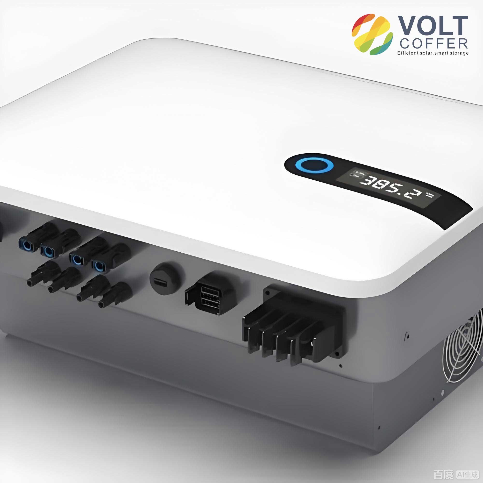
The operation of this polymorphic grid-connected inverter can be understood by examining its switching states. Each phase can output one of four voltage levels corresponding to the connected DC source or zero: \(U_{pv}\), \(U_{fu}\), \(U_{bat}\), or 0. This is defined by specific switch combinations. For a phase \( \phi \) (a, b, c), the output voltage \( V_{\phi n} \) and the corresponding switch states \( S_{\phi} \) are summarized below:
| Switching State \( S_{\phi} \)** | Output Voltage \( V_{\phi n} \)** | Switch Pattern (Sφ1,Sφ2,Sφ3,Sφ4,Sφ5,Sφ6)** |
|---|---|---|
| h | \(U_{pv}\) | 1,1,1,0,0,0 |
| m | \(U_{fu}\) | 0,1,1,1,0,0 |
| l | \(U_{bat}\) | 0,0,1,1,1,0 |
| 0 | 0 | 0,0,0,1,1,1 |
The combination of states across the three phases generates a complex space vector diagram. Unlike standard multilevel inverters with balanced DC-link voltages, the vectors here are asymmetrical because \(U_{fu}\) and \(U_{bat}\) are independent and not fixed fractions of \(U_{pv}\). This asymmetry precludes the use of standard modulation techniques. The space vector diagram for sector I is partially represented by the following key vector classifications:
| Vector Class | |
|---|---|
| Zero Vectors | [0,0,0], [l,l,l], [m,m,m], [h,h,h] |
| Small Vectors | [m,0,0], [l,0,0], [h,m,m], [h,h,l] |
| Medium Vectors | [h,m,0], [h,l,0], [h,m,l] |
| Large Vectors | [h,0,0], [h,h,0] |
The cornerstone of controlling this advanced grid-connected inverter is a Virtual Space Vector Pulse Width Modulation (VSVPWM) strategy. This method is essential to manage the power flow from each DC port independently under unbalanced DC voltage conditions. The strategy involves constructing “virtual” vectors from a linear combination of actual switching vectors that have known and opposing effects on the current drawn from a specific DC port.
Two primary operating modes (Case 1 and Case 2) are defined to facilitate both charging and discharging of the battery.
• Case 1 (Battery Discharge Focus): Virtual vectors are constructed to primarily control fuel cell power, allowing the battery to only discharge. The virtual vectors \(V_{vir1}\) and \(V_{vir2}\) in Sector I are defined as:
$$
V_{vir1} = k_1[l,0,0] + k_2[m,0,0] + (1-k_1-k_2)[h,m,m]
$$
$$
V_{vir2} = k_1[l,l,0] + k_2[m,m,0] + (1-k_1-k_2)[h,h,m]
$$
Here, \(k_1\) and \(k_2\) are control parameters between 0 and 1, with \(k_1+k_2 \leq 1\). The vector \([m,0,0]\) sources power from the fuel cell, \([h,m,m]\) sinks power to it, and \([l,0,0]\) sources power from the battery. Adjusting \(k_1\) and \(k_2\) redistributes power among the sources.
• Case 2 (Battery Charge/Discharge): To enable battery charging, a different set of vectors is used. The virtual vectors are:
$$
V_{vir1} = k_1[h,l,l] + k_2[m,l,l] + (1-k_1-k_2)[l,0,0]
$$
$$
V_{vir2} = k_1[h,h,l] + k_2[m,m,l] + (1-k_1-k_2)[l,l,0]
$$
In this case, \([h,l,l]\) sinks power into the battery, while \([l,0,0]\) sources power from it, enabling bidirectional battery control.
The modulation process involves sector identification (dividing the 60° sector into smaller regions based on the virtual vectors) and calculating the dwell times for the three nearest vectors (\(V_0, V_1, V_2\)) to synthesize the reference voltage \(V_{ref}\). The fundamental equation is:
$$
\begin{aligned}
V_{\alpha} T_s &= V_{0\alpha} T_0 + V_{1\alpha} T_1 + V_{2\alpha} T_2 \\
V_{\beta} T_s &= V_{0\beta} T_0 + V_{1\beta} T_1 + V_{2\beta} T_2 \\
T_s &= T_0 + T_1 + T_2
\end{aligned}
$$
where \(T_s\) is the switching period. If \(V_0\) is a virtual vector, its dwell time \(T_0\) is further decomposed into the dwell times of its constituent actual vectors using the factors \(k_1\) and \(k_2\).
The overall control strategy for this multi-port grid-connected inverter integrates both DC-side energy management and AC-side grid connection requirements. It employs a dual-loop control structure.
DC-Side Control & Energy Management:
The DC-side controller manages power sharing based on source availability and state. The PV port typically operates under Maximum Power Point Tracking (MPPT). The parameters \(k_1\) and \(k_2\) for the VSVPWM are generated by controllers that regulate power or voltage. A key supervisory logic involves the battery’s State of Charge (SOC). A variable \(s\) determines the operating case:
$$
s = \begin{cases}
1 & \text{if } SOC > 15\% \quad \text{(Use Case 1)} \\
0 & \text{if } SOC \leq 15\% \quad \text{(Use Case 2)}
\end{cases}
$$
This logic switches the modulation between Case 1 (battery discharging) and Case 2 (battery charging allowed) to maintain battery health.
AC-Side Control:
The AC-side control ensures proper grid synchronization and power quality. It uses a standard grid-following approach with cascaded power and current loops in the synchronous reference frame (dq-frame). The power loop compares the active and reactive power references (\(P^*, Q^*\)) with measured values and outputs current references (\(i_d^*, i_q^*\)). The current loop then generates the reference voltage signals (\(V_d^*, V_q^*\)), which are transformed to the stationary frame (\(V_\alpha^*, V_\beta^*\)) and fed to the VSVPWM module along with \(k_1\), \(k_2\), and \(s\).
The power capability of each port is a direct function of the modulation parameters \(k_1\), \(k_2\), and the operating case \(s\). The average current from each port over a switching period at angle \(\theta\) can be derived. For example, in a specific sector and case, the currents can be expressed as functions of the phase currents and dwell times. The power from each port is then:
$$
P_{pv} = \frac{U_{pv}}{2\pi} \int_0^{2\pi} i_{pv}(\theta) d\theta, \quad P_{fu} = \frac{U_{fu}}{2\pi} \int_0^{2\pi} i_{fu}(\theta) d\theta, \quad P_{bat} = \frac{U_{bat}}{2\pi} \int_0^{2\pi} i_{bat}(\theta) d\theta
$$
Analysis shows that by varying \(k_1\) and \(k_2\), the power from the fuel cell and battery ports can be flexibly controlled within a defined range. The PV power is consequently adjusted to meet the total grid power demand along with the other sources. The inclusion of Case 2 specifically extends the control range for the battery to include negative power (charging).
The proposed single-stage multi-port grid-connected inverter offers several significant advantages for polymorphic energy systems:
1. High Efficiency: By enabling single-stage conversion from all DC sources to the AC grid, it eliminates the losses associated with multiple cascaded power conversion stages (e.g., a DC-DC converter followed by a DC-AC inverter).
2. Integrated Power Management: The topology and its dedicated VSVPWM strategy allow seamless and flexible real-time power sharing among PV, fuel cell, and battery based on availability, demand, and storage status.
3. Structural Simplicity (Relative to Multiple Converters): It reduces the total component count compared to a system using separate converters for each source, potentially leading to lower cost and higher power density.
4. Enhanced Reliability: The ability to operate in multiple modes (e.g., PV+Fuel Cell, Fuel Cell+Battery, all three) provides inherent redundancy. If one source is unavailable, the grid-connected inverter can continue operation using the others.
Validation of this concept requires realistic simulation under various operating scenarios. A hardware-in-the-loop (HIL) platform, combining a real-time simulator (e.g., RTDS) to model the power circuit and a dedicated microcontroller (e.g., TMS320F28377D) to execute the control and modulation algorithms, serves as an effective validation tool. Key parameters for such a simulation are:
| Parameter | |
|---|---|
| Grid Voltage (RMS, line-to-line) | 220 V |
| PV Voltage (\(U_{pv}\)) | 740 – 850 V |
| Fuel Cell Voltage (\(U_{fu}\)) | 480 – 650 V |
| Battery Voltage (\(U_{bat}\)) | 300 – 450 V |
| Switching Frequency (\(f_s\)) | 2.5 kHz |
| Grid Frequency | 50 Hz |
Simulations would demonstrate various modes: PV-only support (with fuel cell absorbing excess or providing bias), fuel cell-only operation (at night), hybrid modes, and bidirectional operation with grid charging. The results would confirm stable operation, proper current tracking, and independent power control from each port, proving the feasibility of this advanced grid-connected inverter system.
In conclusion, the integration of multiple renewable and storage sources is critical for building robust modern grids. The single-stage multi-port grid-connected inverter topology presented here, governed by its sophisticated Virtual Space Vector PWM and integrated energy management strategy, provides an efficient and flexible solution for this challenge. It represents a significant step forward in power converter technology, enabling direct and controlled interfacing of polymorphic energy resources—photovoltaic, fuel cell, and battery—with the AC grid in a single power conversion stage. Future work may explore extensions to other source types, optimization of the topology for reduced switch count, and the development of advanced model-predictive or AI-based control strategies to further enhance the performance of such integrated grid-connected inverter systems.