
The harnessing of solar energy through photovoltaic conversion represents a cornerstone of sustainable power generation. As a pivotal and environmentally friendly renewable resource, the efficiency of energy capture directly influences the economic viability and environmental impact of solar installations. A critical, yet often underestimated, factor that severely compromises this efficiency is the accumulation of dust, dirt, pollen, bird droppings, and other particulates on the surface of solar panels. This layer of soiling scatters and absorbs incoming sunlight, casting shadows and reducing the active area available for photoelectric conversion. In regions with high dust concentration or infrequent rainfall, such as arid and desert environments where large-scale solar farms are frequently deployed, power output losses can be staggering, with studies indicating reductions ranging from 17.4% to over 40%. Consequently, the imperative to maintain the pristine optical condition of solar panels through regular and effective cleaning has become a significant operational challenge. The quest is not merely for cleaning, but for a method that is autonomous, resource-efficient, reliable, and adaptable to the harsh, extensive, and often inaccessible arrays of solar panels.
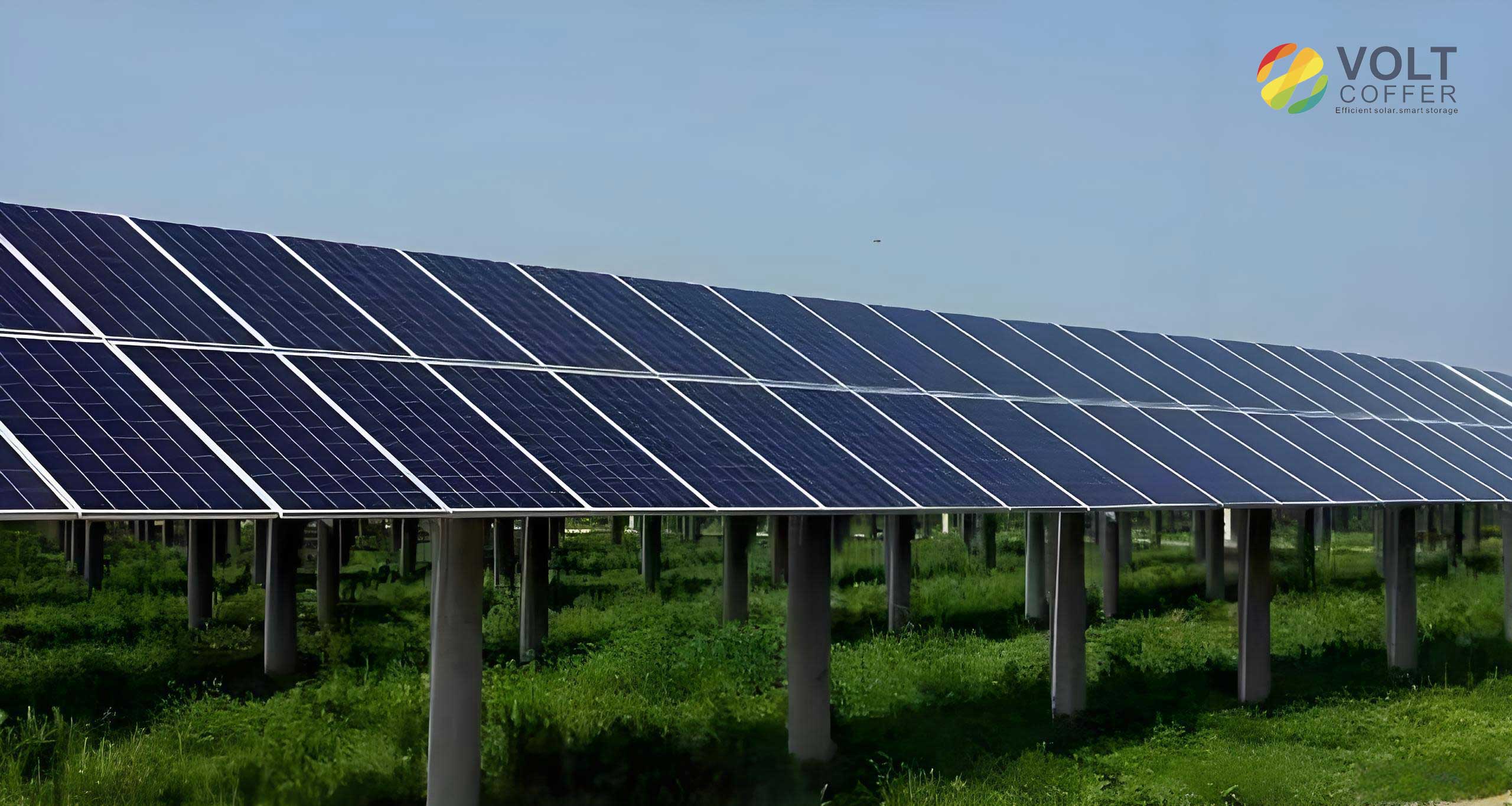
Traditional cleaning methodologies reveal distinct limitations. Manual cleaning with high-pressure water guns, while effective, is labor-intensive, water-profligate, and poses safety risks on large, sloping arrays. The operational cost and logistical difficulty scale poorly with farm size. Robotic cleaners, though promising, often grapple with navigational challenges on uneven terrain, stability issues in windy conditions, and high capital costs. Other nascent technologies like electrodynamic screens are currently more suited to small-scale applications. Therefore, this article presents a comprehensive design for an automated cleaning device, engineered to traverse the arrays of solar panels systematically, performing on-demand cleaning to maximize their light-catching capability and, by extension, their annual energy yield.
1. Holistic Design and Architecture of the Automated Cleaning System
The proposed automatic cleaning system is a synergistic integration of precision mechanics and intelligent control. Its primary mission is to navigate predefined pathways along arrays of solar panels, detect soiling levels, and execute a multi-stage cleaning sequence—rinsing, detergent application, and mechanical scrubbing—without human intervention. The design philosophy prioritizes reliability, energy autonomy, and minimal environmental impact.
The core of the system is a dedicated cleaning vehicle. Its design requirements are multifaceted:
- Mobility & Navigation: The vehicle must move smoothly and reliably along guiding rails installed between rows of solar panels. It must handle slight inclines, start, stop, and reverse direction autonomously upon reaching the end of a rail track.
- Cleaning Process Control: The system must intelligently control the application of water and eco-friendly cleaning solution, minimizing waste. This involves precise activation of pumps and the deployment of a scrubbing mechanism based on sensor inputs.
- System Stability & Autonomy: The vehicle must be self-powered for an entire operational day. Its control system must be robust, with fast sensor signal processing and reliable execution of sequential logic to ensure consistent performance in outdoor conditions.
The physical architecture of the cleaning vehicle can be broken down into two major subsystems: the locomotion drive and the cleaning manipulator. The locomotion system employs an independent wheel-drive configuration. Each driven wheel is powered by its own dedicated Permanent Magnet Synchronous Motor (PMSM) coupled with a reducer. This “wheel-side motor” approach offers superior control, eliminates complex mechanical transmissions (like drive shafts), improves mass distribution, and enhances overall energy efficiency. The cleaning subsystem consists of a multi-degree-of-freedom manipulator arm. This arm is tasked with positioning a cleaning head (equipped with spray nozzles and a rotating brush) flush against the surface of the solar panels. The arm’s articulated joints are actuated by high-torque DC servo motors, allowing it to adapt to the panel’s angle and maintain optimal contact pressure during the scrub cycle.
2. Design and Parameter Matching for the Drive System
The propulsion system is the workhorse of the vehicle. Selecting and matching the drive motor parameters is critical to ensure the vehicle can overcome all resistance forces under various operating conditions. The matching process follows a systematic analysis of the vehicle’s power demands during distinct kinematic states.
The total tractive force required to move the vehicle is a sum of rolling resistance, gradient resistance, aerodynamic resistance, and acceleration force. The power demand is calculated for three key scenarios to determine the peak requirement.
2.1 Power Calculation for Maximum Speed on Level Ground
When the vehicle is traveling at its designated maximum speed ($v_{max}$) on a horizontal guide rail, the required power ($P_{max1}$) is dictated by rolling and aerodynamic drag:
$$
P_{max1} = \frac{v_{max}}{3,600 \eta} \left( mgf + \frac{C_D A v_{max}^2}{21.15} \right)
$$
Where:
$m$ = Total vehicle mass (kg)
$g$ = Gravitational acceleration (9.81 m/s²)
$f$ = Coefficient of rolling resistance
$C_D$ = Aerodynamic drag coefficient
$A$ = Frontal area of the vehicle (m²)
$\eta$ = Overall efficiency of the drive train (motor + reducer)
$v_{max}$ = Maximum design speed (km/h)
2.2 Power Calculation for Climbing Maximum Incline
A more demanding condition is traversing the steepest anticipated incline ($\alpha_{max}$) at a specified speed ($v_{i_{max}}$). The power ($P_{max2}$) must overcome both rolling resistance and the gravitational component:
$$
P_{max2} = \frac{v_{i_{max}}}{3,600 \eta} \left( mgf \cos\alpha_{max} + mg \sin\alpha_{max} \right)
$$
2.3 Power Calculation for Acceleration
During startup or speed changes, additional power ($P_{max3}$) is needed to provide the inertial force for acceleration:
$$
P_{max3} = \frac{v_i}{3,600 t_a \eta} \left( \frac{\delta m \mu_t^2}{2 t_a} + mgf \mu_1^{1.5} + \frac{C_D A \mu_3^t}{21.15 \times 2.5 t_a} \right)
$$
Where:
$t_a$ = Desired acceleration time (s)
$\mu_t$ = Terminal velocity after acceleration (m/s)
$\delta$ = Rotational mass conversion factor ( >1 )
$\mu_1, \mu_3$ are coefficients related to the velocity profile during acceleration.
2.4 Drive Motor Specification
The drive motor must be sized to handle the peak power demand from the most strenuous condition:
$$
P_{motor\_req} \ge \max(P_{max1}, P_{max2}, P_{max3})
$$
For a vehicle with a total mass $m = 1000$ kg, $v_{max} = 8$ km/h, $f=0.25$, $\alpha_{max}=30^\circ$, and assuming standard values for $C_D$ and $A$, the calculations yield $P_{max2}$ as the limiting condition, approximately 11.6 kW. Factoring in a safety margin and the independent drive of two wheels, two PMSM units, each rated at a minimum of 7.5 kW, are selected. Their speed-torque characteristic must provide high starting torque and efficient operation across the expected speed range. The superior power density, high efficiency, and excellent controllability of PMSMs make them ideal for this electric traction application.
| Parameter | Symbol | Value | Unit |
|---|---|---|---|
| Vehicle Mass | $m$ | 1000 | kg |
| Max Speed (Level) | $v_{max}$ | 8 | km/h |
| Max Incline Speed | $v_{i_{max}}$ | 5 | km/h |
| Max Incline Angle | $\alpha_{max}$ | 30 | deg |
| Rolling Resistance Coeff. | $f$ | 0.25 | – |
| Calculated Power (Max Speed) | $P_{max1}$ | ~8.1 | kW |
| Calculated Power (Max Incline) | $P_{max2}$ | ~11.6 | kW |
| Calculated Power (Acceleration) | $P_{max3}$ | ~8.4 | kW |
| Required Motor Power (Total) | $P_{motor\_req}$ | >11.6 | kW |
| Selected Motor Power (x2) | $P_{motor}$ | 7.5 kW each | kW |
| Motor Type | – | Permanent Magnet Synchronous Motor (PMSM) | – |
3. Kinematic and Dynamic Analysis of the Cleaning Manipulator
The cleaning manipulator is a two-link robotic arm responsible for the precise deployment of the cleaning head. Link 1 (length $l_1$) rotates relative to the vehicle’s pillar with an angle $\theta_1$, actuated by Servo Motor D1. Link 2 (length $l_2$) is the cleaning head assembly, rotating relative to Link 1 with an angle $\theta_2$, actuated by Servo Motor D2. This design allows the cleaning head to conform to the plane of the solar panels, maintaining full-surface contact regardless of the panel’s tilt angle.
A dynamic model using the Lagrangian formulation is developed to determine the torque requirements for the servo motors. The system’s kinetic energy ($E$) and potential energy ($V$) are formulated considering point masses $m_1$ (at joint B, representing motor D1 mass) and $m_2$ (at the end of Link 2, representing the cleaning head).
Velocities are derived from geometric relationships:
$$ v_B = l_1 \dot{\theta}_1 $$
$$ v_C^2 = l_1^2 \dot{\theta}_1^2 + l_2^2 (\dot{\theta}_1 + \dot{\theta}_2)^2 + 2 l_1 l_2 \dot{\theta}_1 (\dot{\theta}_1 + \dot{\theta}_2) \cos\theta_2 $$
The kinetic and potential energies are:
$$ E = \frac{1}{2} m_1 l_1^2 \dot{\theta}_1^2 + \frac{1}{2} m_2 \left[ l_1^2 \dot{\theta}_1^2 + l_2^2 (\dot{\theta}_1 + \dot{\theta}_2)^2 + 2 l_1 l_2 \dot{\theta}_1 (\dot{\theta}_1 + \dot{\theta}_2) \cos\theta_2 \right] $$
$$ V = -m_1 g l_1 \cos\theta_1 – m_2 g \left[ l_1 \cos\theta_1 + l_2 \cos(\theta_1 + \theta_2) \right] $$
The Lagrangian $L = E – V$ is used with the Euler-Lagrange equation to derive the equations of motion, which take the general form:
$$ M_1 = D_{11} \ddot{\theta}_1 + D_{12} \ddot{\theta}_2 + D_{111} \dot{\theta}_1^2 + D_{122} \dot{\theta}_2^2 + D_{112} \dot{\theta}_1 \dot{\theta}_2 + D_{121} \dot{\theta}_2 \dot{\theta}_1 + D_1 $$
$$ M_2 = D_{21} \ddot{\theta}_1 + D_{22} \ddot{\theta}_2 + D_{211} \dot{\theta}_1^2 + D_{222} \dot{\theta}_2^2 + D_{212} \dot{\theta}_1 \dot{\theta}_2 + D_{221} \dot{\theta}_2 \dot{\theta}_1 + D_2 $$
Where $M_1$ and $M_2$ are the torques required at Joint 1 and Joint 2, respectively, and the $D$ coefficients are functions of masses, lengths, and angles.
Substituting realistic parameters—$m_1 = 110$ kg, $m_2 = 20$ kg, $l_1 = 1.2$ m, $l_2 = 0.25$ m, with operational ranges $\theta_1 \in [30^\circ, 80^\circ]$ and $\theta_2 \in [30^\circ, 120^\circ]$—the maximum torques are calculated. Servo Motor D1 must produce a peak torque of approximately 950 N·m to move the arm, while Servo Motor D2 must provide about 100 N·m to orient the cleaning head. High-torque DC servo motors are selected for their precise positional control, rapid response, and ability to deliver high torque at low speeds, which is essential for the slow, forceful scrubbing motion against the solar panels.
4. Control System Architecture and Software Logic
The brain of the automated cleaning system is a Programmable Logic Controller (PLC), specifically chosen for its ruggedness, reliability, and suitability for industrial sequential control. The selected PLC model offers robust digital and analog I/O handling, built-in communication ports, and powerful programming capabilities to manage the multi-step cleaning sequence and vehicle navigation.
The control logic is designed as a state-based sequence, triggered by sensor inputs. The primary sensors include:
- Light-Dependent Resistor (LDR) Sensor: Acts as a soiling detector. A significant drop in reflected light intensity from the surface of the solar panels indicates the presence of dust, triggering the cleaning cycle.
- Infrared Distance Sensor: Monitors the vehicle’s position along the rail. When the vehicle approaches the end-of-track, it sends a signal to initiate a reversal sequence.
- Humidity Sensor: Mounted near the cleaning head, it detects when the panel surface has been sufficiently wetted, signaling the controller to switch from the water rinse phase to the detergent application phase.
- Hall-Effect Sensor: Used for measuring wheel rotation, providing feedback for vehicle speed and distance traveled.
The core control sequence is as follows:
- Initiation & Travel: Upon system start, the drive motors engage, propelling the vehicle forward along the rail. The LDR continuously monitors the solar panels.
- Soiling Detection & Rinse: If the LDR detects soiling below a set threshold, the vehicle stops. The water pump motor is activated, spraying clean water onto the soiled section of the solar panels.
- Detergent Application: The humidity sensor confirms adequate wetting. The water pump stops, and a solenoid valve for the detergent line opens for a precisely timed interval (e.g., 2-3 seconds).
- Mechanical Scrubbing: Following detergent application, the servo motor driving the rotating brush is activated. The cleaning manipulator ensures full-contact, and the brush scrubs the area for a fixed duration (e.g., 10 seconds).
- Cycle Completion & Resume: After scrubbing, all cleaning actuators turn off. The vehicle drive motors re-engage, moving the system to the next section of solar panels.
- End-of-Track Reversal: When the distance sensor detects the end of the rail, the drive motors are commanded to reverse, returning the vehicle to its starting point for the next scheduled operation.
| Symbol | I/O Address | Type | Description / Function |
|---|---|---|---|
| START | %IX0.0 | Digital Input | Main System Start Button |
| Soiling_Sig | %IX0.1 | Analog/Digital Input | Signal from LDR Soiling Sensor |
| Humidity_Sig | %IX0.2 | Analog Input | Signal from Surface Humidity Sensor |
| Dist_End_Sig | %IX0.3 | Analog Input | Signal from End-of-Track Distance Sensor |
| STOP_EMG | %IX0.6 | Digital Input | External Emergency Stop Button |
| Drive_Fwd | %QX1.1 | Digital Output | Command to Drive Motors (Forward) |
| Drive_Rev | %QX1.2 | Digital Output | Command to Drive Motors (Reverse) |
| Pump_Water | %QX1.3 | Digital Output | Control for Water Pump Motor |
| Valve_Detergent | %QX1.4 | Digital Output | Control for Detergent Solenoid Valve |
| Motor_Brush | %QX1.5 | Digital Output | Control for Brush Drive Motor |
| Soiling_Level | %MW300 | Memory Word | Stores processed soiling data from sensor |
The software is structured using ladder logic or structured text within the PLC programming environment. Timers (TON) are extensively used to control the duration of spray and brush operations. Comparison instructions are used to evaluate sensor values against preset thresholds. The logic ensures a fail-safe operation, where any interruption or fault condition defaults the system to a safe stop state.
5. Energy System and Component Selection
For full autonomy, the cleaning vehicle carries its own energy storage system. Lithium Iron Phosphate (LiFePO4) batteries are chosen for their long cycle life, safety, stability, and good performance across a wide temperature range—attributes crucial for outdoor deployment near solar panels.
The battery capacity ($W$) is estimated based on the daily energy consumption of all actuators:
$$
W = \left[ \frac{(P_1 + P_2) T_1}{\eta_1} + \frac{(p_1 + p_2) T_2}{\eta_2} \right] \cdot k
$$
Where:
$P_1, P_2$ = Power of the two main drive motors (kW).
$p_1, p_2$ = Power of the servo and auxiliary motors (kW).
$T_1, T_2$ = Total daily operational time for drive and cleaning systems (h).
$\eta_1, \eta_2$ = Efficiency of respective motor drives.
$k$ = Design margin factor (e.g., 1.2).
For a system with 2x 7.5 kW drives and 0.5 kW of cleaning actuators operating for 10 hours with efficiency factors around 0.9, the required battery capacity is substantial, likely in the range of 400-500 Ah at a system voltage of 48V or 72V. A dedicated Battery Management System (BMS) is integrated to monitor cell voltages, temperatures, and state-of-charge, ensuring safety and prolonging battery life.
| Subsystem | Component Type | Key Selection Criteria | Selected Specification / Model Type |
|---|---|---|---|
| Locomotion | Drive Motor | Peak Power (~7.5 kW), High Starting Torque, Efficiency | Permanent Magnet Synchronous Motor (PMSM) with integrated reducer |
| Manipulation | Servo Motor | High Torque (950 N·m & 100 N·m), Precision Positioning | High-torque DC Servo Motor with encoder feedback |
| Control | Programmable Logic Controller | Ruggedness, Digital/Analog I/O, Communication Ports | Industrial-grade PLC (e.g., HolleySys LM series equivalent) |
| Sensing | Soiling Sensor | Reliability in outdoor light, Sensitivity | Light Dependent Resistor (LDR) or calibrated photodiode sensor |
| Sensing | Distance Sensor | Accuracy, Range, Outdoor durability | Infrared or Ultrasonic Distance Sensor |
| Energy | Battery Pack | Energy Density, Cycle Life, Safety | Lithium Iron Phosphate (LiFePO4) Battery with BMS |
6. Conclusion and Future Perspectives
The design and engineering of an automatic cleaning system for solar panels present a compelling solution to the pervasive problem of soiling-induced efficiency losses. The system elaborated herein integrates a robust mechanical platform with independent electric drive, a dynamically modeled manipulator for effective scrubbing, and an intelligent, sensor-driven PLC-based control system. This synergy enables autonomous, efficient, and reliable cleaning of extensive arrays of solar panels, directly translating to higher energy yield and improved return on investment for solar power plants, especially those located in dust-prone regions.
Future iterations of this design could incorporate several advanced features to further enhance performance and reduce resource consumption. The integration of water recovery and filtration systems would minimize water usage, a critical advantage in arid environments. Machine learning algorithms could be implemented on a supervisory level to analyze soiling patterns and optimize cleaning schedules, moving from periodic to predictive maintenance. Furthermore, the deployment of a fleet of such cleaning vehicles coordinated via wireless mesh networks could manage the cleaning of vast solar farms with maximum efficiency. Ultimately, as the global footprint of solar panels continues to expand, the role of intelligent, automated cleaning and maintenance systems will become indispensable in safeguarding their performance and ensuring the sustainability of solar energy as a primary power source for the future.