
As an engineer specializing in industrial structural assessments, I have witnessed a significant shift towards renewable energy integration in recent years. The proliferation of distributed photovoltaic systems, particularly the installation of solar panels on existing factory roofs, presents both opportunities and challenges. Gabled frame steel structure factories, with their large, unobstructed roof areas, are prime candidates for hosting solar panels. However, these structures are often designed as lightweight, long-span systems sensitive to additional loads. The introduction of solar panels, which contribute permanent dead load and may alter wind and snow load distributions, necessitates a thorough structural appraisal and potential reinforcement to ensure safety over the remaining service life. This article details, from my professional perspective, the systematic methodology for appraising and reinforcing such factories, emphasizing the critical impact of solar panels.
The process begins with a comprehensive understanding of the factory’s current state. A typical single-span gabled frame steel structure factory might have dimensions around 48m in length and 17.6m in span, with an eave height of 6.5m and a ridge height of 7.5m. The primary frame consists of welded H-section steel beams and columns, with cold-formed C-section purlins supporting a lightweight roof cladding system. Before any solar panel installation, it is imperative to conduct a detailed appraisal. This appraisal is not merely a formality; it is a vital engineering process to diagnose the structure’s capacity and identify vulnerabilities exacerbated by the new loads from solar panels.
The appraisal protocol I follow is multi-faceted, encompassing document review, geometric surveys, material testing, condition assessment, and detailed structural analysis. The geometric survey involves measuring the actual dimensions of structural members to verify compliance with original drawings and tolerances. For instance, the cross-sectional dimensions of beams, columns, and purlins are meticulously recorded. The results for primary members can be summarized as follows:
| Member Type | Nominal Section | Average Measured Depth, h (mm) | Average Measured Flange Width, b (mm) | Average Web Thickness, t_w (mm) | Average Flange Thickness, t_f (mm) |
|---|---|---|---|---|---|
| Steel Beam | H400x200 | 395.7 | 200.5 | 6.2 | 10.2 |
| Steel Column | H400x200 | 400.6 | 200.5 | 8.1 | 12.2 |
| Roof Purlins | C220x75x20 | 220.4 | 75.4 | 2.5 (thickness) | N/A |
Material strength is another critical parameter. Using a portable hardness tester, I determine the tensile strength of the steel. The conversion from hardness to tensile strength follows an empirical relationship. For carbon steel, a common approximation is given by:
$$ \sigma_b = k \cdot H $$
where $\sigma_b$ is the tensile strength (N/mm²), $H$ is the hardness value (e.g., Leeb), and $k$ is a correlation factor typically around 3.0-3.2 for structural steel. Testing multiple locations on sampled beams and columns yields results like those below, confirming the steel grade (e.g., Q235B with a tensile strength range of 375-500 N/mm²).
| Sample Location | Estimated Tensile Strength Lower Bound (N/mm²) | Estimated Tensile Strength Upper Bound (N/mm²) | Mean Estimated Tensile Strength (N/mm²) |
|---|---|---|---|
| Beam (Mid-span) | 383 | 533 | 458 |
| Column (Base) | 388 | 538 | 463 |
| Beam (Near Support) | 384 | 534 | 459 |
A thorough visual and instrumental condition survey is conducted to check for deformations, corrosion, connection integrity, and compliance with detailing requirements. Special attention is paid to bracing systems, including ridge braces, eave struts, and knee braces (or lack thereof), as these are crucial for the stability of lightweight frames, a factor made more critical under the new loading regime from solar panels. The survey also documents the existing dead loads (roofing, purlins) and confirms the absence of unaccounted loads like cranes or roof悬挂.
The core of the appraisal is the structural analysis and capacity check under the updated load combinations that include the solar panels. The additional load from solar panels is not negligible. A typical photovoltaic system, including panels, mounting rails, and connectors, can add a permanent dead load ($G_{pv}$) of 0.15 to 0.25 kN/m² on the roof plane. This must be combined with existing dead loads ($G_{k}$), live loads ($Q_{k}$), wind ($W_{k}$), and snow ($S_{k}$) according to the relevant design code, such as the load combination principles in limit state design:
$$ S_d = \gamma_G (G_k + G_{pv}) + \gamma_Q Q_k + \psi_c \gamma_W W_k + … $$
where $S_d$ is the design load effect, $\gamma_G$ and $\gamma_Q$ are partial factors for permanent and variable actions, and $\psi_c$ is a combination factor. For preliminary assessment, one can calculate the increase in purlin bending moment. For a simply supported purlin under uniformly distributed load (UDL), the moment is:
$$ M = \frac{w L^2}{8} $$
where $w$ is the total UDL per unit length and $L$ is the span. Adding solar panel load $\Delta w_{pv}$ increases the moment proportionally:
$$ \Delta M = \frac{\Delta w_{pv} L^2}{8} $$
This simple calculation often reveals that purlins, being the most lightweight members, are the first to exceed their capacity when solar panels are added.
For the primary gabled frame, I create a computational model using structural analysis software. The model incorporates the measured geometry, material properties, and all loads, with the solar panel load applied as an additional surface dead load on the roof. The analysis outputs member forces (axial force $N$, bending moment $M$, shear force $V$), which are then checked against the member capacities. The key check is the unity check or stress ratio ($R$) for each limit state. For a beam-column member, checks typically include:
1. Cross-sectional strength (yield check):
$$ R_1 = \frac{N}{A_n f_y} + \frac{M_x}{\gamma_x W_{nx} f_y} + \frac{M_y}{\gamma_y W_{ny} f_y} \leq 1.0 $$
where $A_n$ is net area, $W_{nx}$ is elastic section modulus, $f_y$ is yield strength, and $\gamma$ is plasticity development coefficient.
2. In-plane buckling strength:
$$ R_2 = \frac{N}{\varphi_x A f_y} + \frac{\beta_{mx} M_x}{\gamma_x W_{1x} (1 – 0.8N/N’_{Ex}) f_y} \leq 1.0 $$
where $\varphi_x$ is the reduction factor for buckling, $\beta_{mx}$ is an equivalent moment factor, and $N’_{Ex}$ is the Euler buckling load.
3. Out-of-plane buckling strength:
$$ R_3 = \frac{N}{\varphi_y A f_y} + \frac{\beta_{tx} M_x}{\varphi_b W_{1x} f_y} \leq 1.0 $$
where $\varphi_b$ is the stability factor for bending.
In a typical appraisal for a factory slated for solar panel installation, my analysis often reveals stress ratios exceeding 1.0 for several members, especially purlins and sometimes the primary beams in terms of out-of-plane stability. The following table might summarize the critical stress ratios for a representative frame before considering reinforcement:
| Component | Location | Bending Strength Stress Ratio, $R_1$ | In-Plane Stability Stress Ratio, $R_2$ | Out-of-Plane Stability Stress Ratio, $R_3$ | Code Limit |
|---|---|---|---|---|---|
| Rafter Beam | Mid-span region | 1.20 | 1.14 | 1.58 | 1.00 |
| Column | Upper segment | 1.12 | 1.11 | 1.53 | 1.00 |
| Roof Purlin (Simply Supported) | Mid-span | 1.53 (Bending) | N/A | 1.68 (Lateral-Torsional Buckling under wind uplift) | 1.00 |
These results clearly indicate that the structure, in its current state, cannot safely accommodate the additional load from the proposed solar panels. The purlins are particularly overstressed. This necessitates the design and implementation of a reinforcement scheme. The choice of reinforcement strategy is guided by principles of efficiency, minimal disruption, and cost-effectiveness. Broadly, methods are categorized into direct member strengthening (e.g., section enlargement, bonded steel plates) and indirect system strengthening (modifying the structural system to reduce internal forces or effective lengths). For gabled frame factories with solar panels, I often find indirect methods to be highly effective and less intrusive.
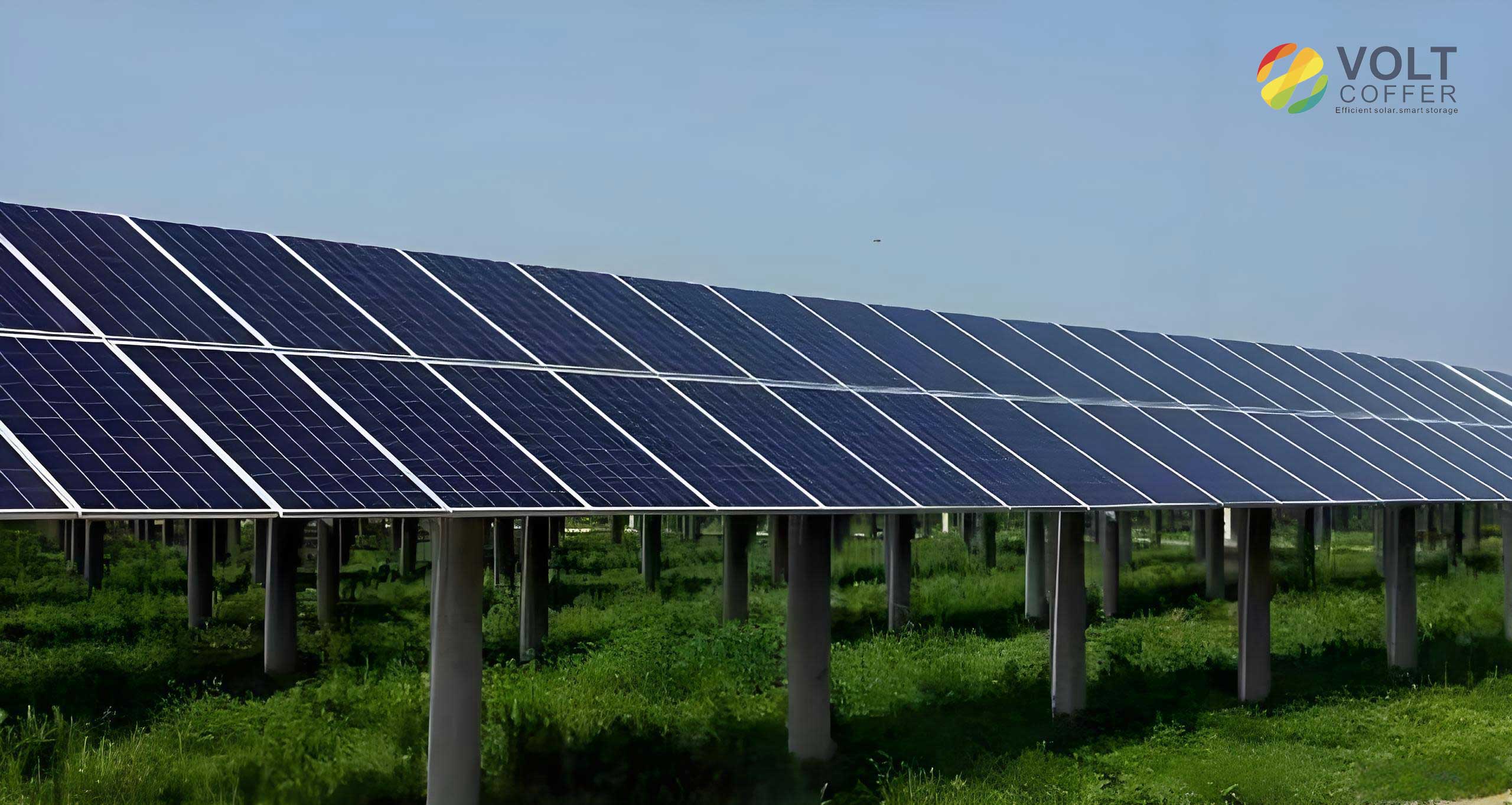
The visual above represents the end goal: a robust factory roof seamlessly integrated with an array of solar panels. To achieve this safely, the structure beneath must be adequately reinforced. My reinforcement strategy typically involves a multi-step approach targeting the specific failure modes identified:
Step 1: Enhance Lateral Stability of Rafters (Address High $R_3$). The high out-of-plane stress ratio for the rafter beam is often due to an excessive unbraced length. Installing additional purlin braces or knee braces from the rafter to the purlins can significantly reduce the effective length for lateral-torsional buckling. The critical elastic moment for lateral-torsional buckling is proportional to the inverse of the unbraced length ($L_b$):
$$ M_{cr} \propto \frac{\sqrt{E I_y G J}}{L_b} $$
where $E$ is Young’s modulus, $I_y$ is the minor axis moment of inertia, $G$ is the shear modulus, and $J$ is the torsional constant. Halving $L_b$ can nearly quadruple $M_{cr}$, dramatically reducing the stress ratio.
Step 2: Reduce Span/Effective Length of Primary Members. For high in-plane stress ratios ($R_1$, $R_2$) in rafters and columns, introducing additional bracing within the plane of the frame can be highly effective. Adding diagonal braces between columns and rafters, creating a truss-like action, reduces the bending moment in the rafter. The rafter can be idealized as a continuous beam on elastic supports. The maximum moment in a uniformly loaded beam is proportional to the square of the span ($L$):
$$ M_{max} \propto w L^2 $$
Introducing a central support (via a diagonal brace connected to a column) effectively reduces the span for bending calculations, thereby reducing the moment. The force in a diagonal brace ($F_{brace}$) under a point load $P$ at mid-span (representing the effect of redistributed load) can be approximated from static equilibrium of a truss node:
$$ F_{brace} = \frac{P}{\sin \theta} $$
where $\theta$ is the angle of the brace relative to the horizontal.
Step 3: Upgrade Purlin System. This is often the most crucial step when adding solar panels. Converting simply supported purlins into continuous purlins over multiple spans drastically reduces the maximum bending moment. For a two-span continuous purlin under UDL $w$, the maximum moment over the interior support is:
$$ M_{support} = \frac{w L^2}{8} $$
while the positive moment in the span is reduced to approximately $\frac{w L^2}{16}$. This is a significant improvement over the simply supported moment of $\frac{w L^2}{8}$ at mid-span. The connection at the purlin laps must be designed to transfer the negative moment, typically using high-strength bolts or through-plates. The capacity check for a continuous purlin involves checking both positive and negative moment regions, as well as shear and web crippling at supports.
Step 4: Strengthen Column Stability. If column stress ratios, particularly out-of-plane ($R_3$), are high, adding horizontal tie rods or struts between columns at the mid-height or along the eave can reduce the effective length for minor-axis buckling. The buckling load is given by Euler’s formula:
$$ P_{cr} = \frac{\pi^2 E I}{{(K L)}^2} $$
where $K$ is the effective length factor. Providing intermediate lateral support changes $K$ from 1.0 (pinned-pinned) to 0.5 (pinned-fixed with mid-point support), effectively quadrupling the buckling load.
After designing and applying such reinforcement measures, I re-analyze the structure. The results typically show a dramatic improvement. The following table contrasts the stress ratios before and after a typical reinforcement scheme involving added rafter braces, diagonal frame bracing, and conversion to continuous purlins:
| Component | Critical Stress Ratio (Before Reinforcement) | Critical Stress Ratio (After Reinforcement) | Reinforcement Measure Applied |
|---|---|---|---|
| Rafter Beam (Out-of-Plane Stability) | 1.58 | 0.62 | Added knee braces at every other purlin point. |
| Rafter Beam (In-Plane Bending) | 1.20 | 0.66 | Added one diagonal brace from ridge to column mid-height. |
| Column (Out-of-Plane Stability) | 1.53 | 0.90 | Added horizontal eave strut connecting all columns. |
| Roof Purlin (Bending & Stability) | 1.53 / 1.68 | 0.67 / 0.72 | Converted to 2-span continuous system with moment-resisting connections at lap joints. |
The reinforcement design must comply with contemporary codes, such as the standard for strengthening steel structures. All new connections are designed for the transferred forces, considering prying action and bolt shear capacity. The capacity of a bolted connection in shear is checked as:
$$ V_{Rd} = n \cdot F_{v,Rd} $$
where $n$ is the number of bolts and $F_{v,Rd}$ is the design shear resistance per bolt, calculated as $0.6 f_{ub} A_s / \gamma_{M2}$ for bolt classes, with $f_{ub}$ being the ultimate tensile strength of the bolt and $A_s$ the tensile stress area.
It is crucial to consider the construction sequence. Reinforcement work should be carried out from the roof downwards to maintain stability, and the installation of solar panels should only commence after all reinforcement is complete and verified. Furthermore, during both reinforcement and subsequent solar panel installation, strict controls must be in place to prevent any unintended roof loading from material stockpiling.
In conclusion, the integration of solar panels onto existing gabled frame steel factories is a technically feasible and economically attractive proposition, but it is not a trivial undertaking. It demands a rigorous, systematic engineering appraisal to quantify the structural impact of the additional loads imposed by the solar panels. This appraisal, involving detailed measurement, testing, and advanced structural analysis, invariably reveals deficiencies in the original lightweight design when subjected to the new loading condition. Fortunately, a suite of indirect reinforcement techniques—focused on modifying the structural system by adding braces, enhancing continuity, and reducing effective lengths—provides an efficient and often minimally invasive solution. These techniques directly address the overstress conditions identified in the appraisal, ensuring that the stress ratios for all members, from the primary frame down to the purlins, are brought within safe limits. By following this disciplined approach of appraisal first, followed by code-compliant, system-based reinforcement, we can safely unlock the vast potential of factory roofs for solar energy generation, contributing to sustainability goals without compromising structural integrity. The successful marriage of existing industrial infrastructure with modern solar technology hinges on this foundational engineering process.