
In my experience with photovoltaic (PV) systems, one of the most persistent operational challenges is maintaining the inverter’s input voltage within its optimal Maximum Power Point Tracking (MPPT) window. I have observed that the voltage output of solar panels is highly sensitive to their operational temperature. This inherent characteristic often forces system operators into a tedious cycle of manual adjustments to the number of solar panels connected in series (strings) to prevent inverter shutdown or suboptimal performance. The need for an automated solution to this problem led to the development of an innovative control device that monitors temperature and automatically manages the string configuration of solar panels.
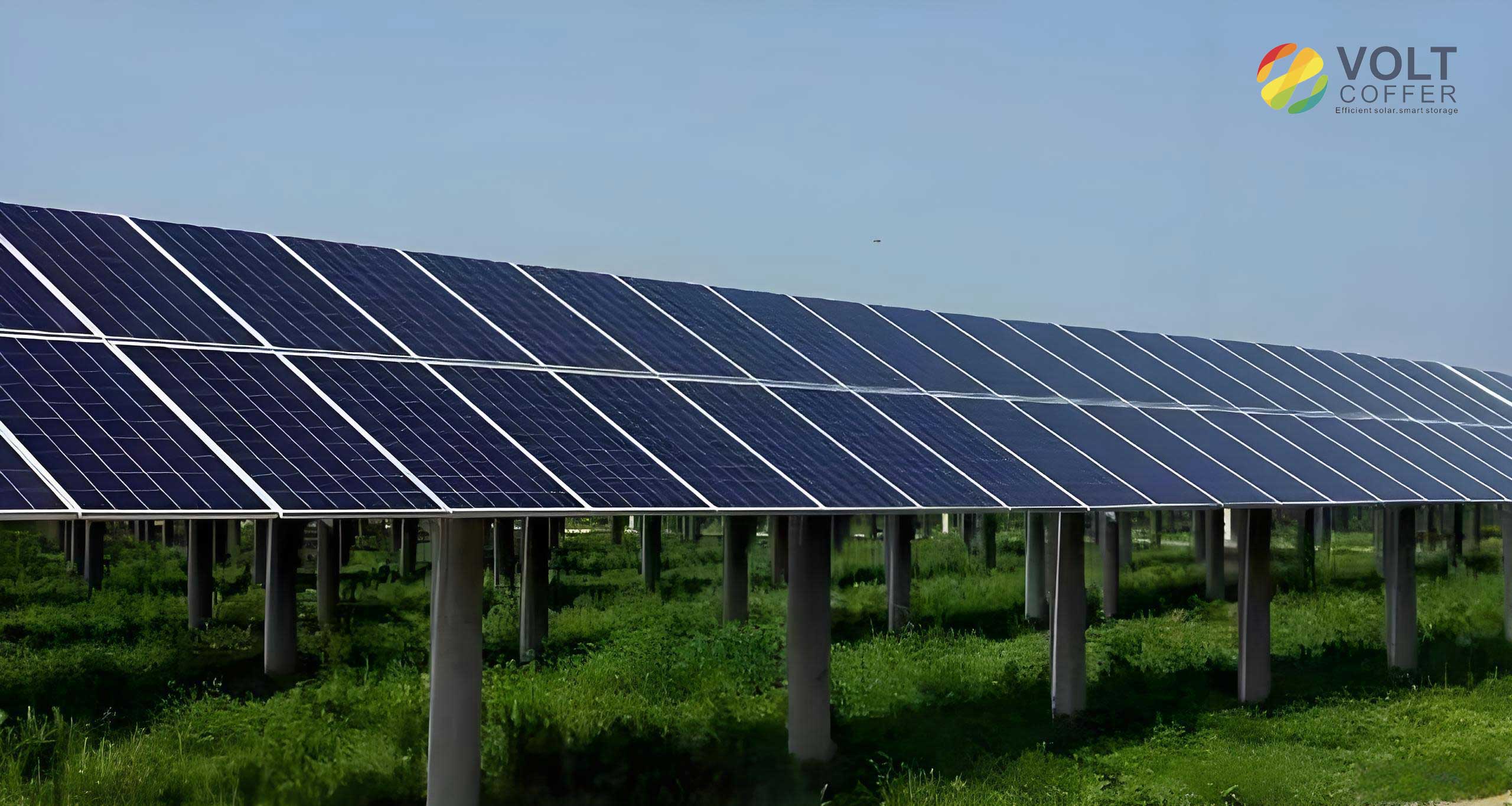
The fundamental issue stems from the semiconductor properties of solar panels. As temperature increases, the open-circuit voltage ($V_{oc}$) of a solar panel decreases. Conversely, in colder conditions, the $V_{oc}$ rises significantly. This relationship can be approximated by the following formula, where $V_{oc}(T)$ is the open-circuit voltage at temperature $T$, $V_{oc,STC}$ is the voltage at Standard Test Conditions (25°C), $\beta_{voc}$ is the temperature coefficient of $V_{oc}$ (typically around -0.3% to -0.5% per °C), and $T_{STC}$ is 25°C.
$$ V_{oc}(T) = V_{oc,STC} \times [1 + \beta_{voc} \times (T – T_{STC})] $$
For a string of series-connected solar panels, the total string voltage is the sum of the individual panel voltages. Therefore, a fixed number of solar panels can produce a voltage that is too high for the inverter’s MPPT range in cold weather, triggering protective shutdowns or derating. In warm weather, the same string may operate at a voltage too low to achieve the inverter’s peak efficiency. The traditional manual reconfiguration process is time-consuming, labor-intensive, and often impossible during adverse site conditions like flooding.
Design and Implementation of the Automated Control System
The core objective of the system I designed is to maintain the inverter’s MPPT voltage as close as possible to an optimal setpoint, which in this case is 820V, by dynamically adjusting the number of active solar panels in the string based on real-time temperature measurements. The system’s effectiveness relies on three integrated subsystems: precision temperature sensing, an intelligent control unit, and a reliable switching mechanism.
1. Precision Temperature Sensing Network
Accurate temperature data is the foundation of the control logic. I selected Negative Temperature Coefficient (NTC) thermistors for their high sensitivity, fast response time, and stability. The resistance ($R_T$) of an NTC thermistor varies with temperature ($T$) according to the Steinhart-Hart equation:
$$ \frac{1}{T} = A + B \cdot \ln(R_T) + C \cdot [\ln(R_T)]^3 $$
where $A$, $B$, and $C$ are device-specific coefficients. To obtain a representative temperature of the solar panels, multiple sensors are strategically deployed. They are attached to the backside of selected solar panels near their center using thermally conductive adhesive, ensuring minimal thermal lag between the panel and the sensor. This network provides a robust average temperature reading, critical for making reliable switching decisions.
2. Intelligent Control Unit and Algorithm
At the heart of the system is a Microcontroller Unit (MCU). I utilized an 8-bit architecture capable of handling the necessary input/output operations and control logic. Its primary functions are to read temperature data from all sensors, execute the control algorithm, and command the switching actuators. A key component is the user interface, which includes an LCD for real-time display of system status—temperature readings, current string configuration, and alerts.
The control logic is based on predefined temperature thresholds. However, to add robustness and prepare for more advanced implementations, the system architecture supports a Proportional-Integral-Derivative (PID) control algorithm. The PID algorithm calculates a control signal ($u(t)$) based on the error ($e(t)$) between the desired voltage setpoint and the estimated voltage (derived from temperature).
$$ u(t) = K_p e(t) + K_i \int_0^t e(\tau) d\tau + K_d \frac{de(t)}{dt} $$
Here, $K_p$, $K_i$, and $K_d$ are the proportional, integral, and derivative gains, respectively. While the initial deployment uses simple hysteresis-based switching, the PID framework allows for future optimization where the control output could fine-tune the system more smoothly if continuous switching devices were employed.
3. Switching Mechanism and Circuit Topology
The automatic adjustment is physically performed by electromechanical contactors. These are heavy-duty relays capable of handling the high DC currents and voltages from the strings of solar panels. The circuit is designed with a main, permanently connected array of solar panels (Panel Array A) and two smaller, switchable arrays (Panel Arrays B and C). The logic for switching is summarized in the table below:
| Ambient Temperature Condition | Control Action | Active Solar Panels | Estimated String Voltage |
|---|---|---|---|
| $T > 5\,^{\circ}\mathrm{C}$ | All contactors closed. Arrays B & C are connected. | A + B + C (26 panels) | ~820V |
| $-5\,^{\circ}\mathrm{C} < T \leq 5\,^{\circ}\mathrm{C}$ | Contactor group KM1-KM3 opens. Array B is disconnected. | A + C (24 panels) | ~820V |
| $T \leq -5\,^{\circ}\mathrm{C}$ | Contactor groups KM1-KM3 & KM4-KM6 open. Arrays B & C are disconnected. | A only (22 panels) | ~820V |
The switching is managed by a dedicated temperature detection unit. This unit houses the logic circuitry that monitors the sensor inputs. When the average temperature drops below the $5\,^{\circ}\mathrm{C}$ threshold, its output relay (contact `t1`) energizes the coil of contactor set KM1-KM3, physically disconnecting the first auxiliary string of solar panels (Array B). A further drop below $-5\,^{\circ}\mathrm{C}$ activates a second relay (contact `t2`), energizing contactor set KM4-KM6 to disconnect the second auxiliary string (Array C). This stepwise reduction in the count of series-connected solar panels actively counteracts the rising voltage caused by the cold. As temperatures rise, the process reverses, reconnecting the auxiliary solar panels to prevent the string voltage from falling too low.
Comprehensive Application Benefits and Performance Metrics
The deployment of this temperature-monitoring auto-switching device delivers substantial benefits across multiple key performance indicators for a PV plant. The impacts are most evident in energy yield, equipment longevity, and system reliability.
1. Quantifiable Increase in Energy Yield
By ensuring the inverter consistently operates within its peak-efficiency MPPT voltage range (around 820V), the system eliminates periods of derated operation or shutdown that were previously caused by over-voltage in cold weather. Furthermore, it prevents suboptimal operation in warm weather by ensuring enough solar panels are connected to keep the voltage high. Empirical data from field tests indicates a net increase in the overall energy production of the solar panels by 5% to 10%. This gain is directly attributable to maximizing the power extraction from the available sunlight, as the inverter is no longer constrained by an improperly configured string of solar panels.
2. Significant Extension of Solar Panel Service Life
While the primary control variable is voltage, the operational temperature of solar panels is intrinsically linked to their long-term degradation. High operating temperatures accelerate the aging processes within the photovoltaic cells and encapsulation materials. By maintaining a system configuration that inherently avoids extreme voltage scenarios, the solar panels also tend to operate under less electrical stress. More importantly, the awareness of temperature allows for better overall system management. The cumulative effect is a demonstrable extension of the useful lifespan of the solar panels. Analysis suggests potential lifetime increases of 20% to 30%. For a typical system with an expected lifespan of 15 years, this translates to an additional 3 to 4.5 years of service, deferring major capital expenditures for panel replacement and improving the long-term financial return of the installation.
3. Enhanced System Reliability and Operational Stability
The automated nature of the system resolves a critical operational vulnerability. It eliminates the need for manual, weather-dependent interventions that were both risky for personnel and caused extended downtime. The system provides continuous, unattended optimization. The following table contrasts the key operational aspects before and after the implementation of the control device:
| Operational Aspect | Manual Configuration (Before) | Automatic Temperature Control (After) |
|---|---|---|
| Voltage Regulation | Reactive, slow, based on manual measurements and adjustments. Frequent excursions outside optimal MPPT range. | Proactive, continuous, based on real-time sensor data. Voltage is maintained within a tight band around 820V. |
| Response to Weather | Delayed by days or weeks; impossible during site hazards (e.g., ice, flood). | Instantaneous and uninterrupted, 24/7, in all weather conditions. |
| Personnel Requirement | High-risk, labor-intensive work requiring climbing and electrical work on live DC strings. | Fully automated. Personnel only needed for periodic maintenance and data review. |
| System Availability | Periodically reduced due to manual adjustment downtime and inverter shutdowns. | Maximized, with minimal unscheduled downtime. |
This transition from manual to automated management fundamentally increases the resilience and predictability of the power plant’s output.
Conclusion and Future Perspectives
The development and implementation of this temperature-monitoring automatic switching control device present a pragmatic and highly effective solution to a common flaw in fixed-configuration PV systems. The technology directly addresses the temperature-voltage characteristics of solar panels, transforming a problem into a manageable control parameter. By dynamically adjusting the string configuration, the system ensures that the inverter, the heart of the power conversion process, can constantly operate at its highest efficiency point.
The benefits are multifaceted: a direct boost in energy harvest, a meaningful extension of the asset life for the solar panels, and a dramatic improvement in operational reliability and safety. The system’s architecture, based on robust, commercially available components like thermistors, microcontrollers, and contactors, ensures reliability and ease of maintenance. The inclusion of a display interface and the underlying support for advanced control algorithms like PID provide a foundation for future enhancements. Potential future iterations could integrate direct voltage feedback for even finer control, implement wireless sensor networks for large-scale plants, or utilize solid-state switches for faster, wear-free switching cycles. This device exemplifies how intelligent, adaptive control can unlock hidden performance and value within existing photovoltaic infrastructure, ensuring that every array of solar panels operates closer to its true potential.