
The integration of solar panels into the building envelope, commonly known as Building-Integrated Photovoltaics (BIPV), represents a significant stride towards sustainable architecture. By serving dual purposes—acting as a building skin element while simultaneously generating electricity—solar panels contribute directly to a structure’s energy needs. However, a critical and often limiting factor in the efficient performance of these integrated solar panels is their operating temperature. It is well-established that the electrical conversion efficiency of photovoltaic cells decreases by approximately 0.4% to 0.5% for every 1°C rise in temperature. In hot climates, the temperature of BIPV modules can soar to 130°C, leading to substantial efficiency losses and potential long-term degradation. Therefore, effective thermal management is not merely an enhancement but a fundamental requirement for optimizing the energy yield and lifespan of rooftop solar panels.
My research focuses on analyzing the heat transfer characteristics of two prevalent rooftop mounting configurations for solar panels. The primary objective is to identify and recommend an installation structure that balances ease of implementation with superior passive cooling performance. This investigation is driven by the need for practical, low-cost cooling solutions that leverage natural phenomena. The core of this study involves establishing detailed thermal models for a parallel mounting structure and a novel lattice (or non-parallel) mounting structure. I validated the numerical approach through experiments on the parallel setup. The findings indicate that the lattice structure, by design, introduces a greater cooling air flux beneath the solar panels. Under identical conditions, for an air channel spacing ranging from 20 mm to 150 mm, the average temperature of both the solar panels and the roof deck decreases with increasing spacing before eventually stabilizing. Crucially, at smaller spacing intervals, the lattice structure maintains significantly lower average temperatures for both the solar panels and the roof compared to the parallel structure. This temperature differential diminishes as the channel spacing increases.
Introduction to Installation Configurations for Solar Panels
The conventional method for installing solar panels on pitched roofs involves mounting them parallel to the roof surface, creating a uniform air gap or channel between the panel backsheet and the roof deck. This setup allows for passive cooling via buoyancy-driven airflow, where heated air rises along the slope, drawing in cooler ambient air from the bottom. While effective to a degree, this parallel structure may not optimally utilize the available wind and thermal buoyancy forces. An alternative approach, which I term the “lattice structure,” arranges the solar panels in a non-parallel fashion. In this configuration, the spacing at the inlet (bottom edge) of the air channel is deliberately made wider than at the outlet (top edge). This tapering design aims to modulate the airflow velocity and pressure distribution, potentially enhancing convective heat removal from the solar panels.
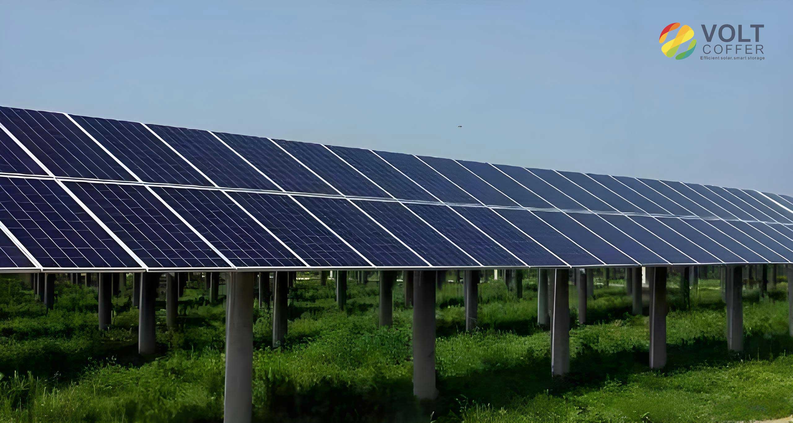
In my analysis, I consider an array comprising three standard solar panels, each with dimensions of 1660 mm in length and 670 mm in width. A standard panel laminate consists of several layers: a 3.2 mm thick glass cover, a 1 mm thick Ethylene-Vinyl Acetate (EVA) encapsulant, a 0.2 mm thick layer of silicon photovoltaic cells, and a 0.3 mm thick Tedlar backsheet. The roof is modeled with a 15° tilt angle, a common pitch for residential buildings. For the parallel structure, all three solar panels are mounted with an identical and constant air gap ‘D’ between the panel and the roof along their entire length. Air is modeled to flow from the bottom inlet to the top outlet. The lattice structure modifies this by setting the inlet spacing between adjacent panels to \( \frac{4}{3}D \) and the outlet spacing to \( \frac{2}{3}D \), creating a converging air channel beneath the central panel. The coordinate system is defined with the flow direction along the positive X-axis and the roof surface at Z=0.
| Feature | Parallel Mounting Structure | Lattice Mounting Structure |
|---|---|---|
| Channel Geometry | Uniform spacing (D) along entire panel length. | Converging channel; inlet wider (\(4D/3\)) than outlet (\(2D/3\)). |
| Primary Cooling Mechanism | Natural convection driven by uniform heating. | Enhanced convection due to varied cross-section affecting flow velocity and pressure. |
| Construction Complexity | Lower. Requires uniform mounting rails. | Higher. Requires precise, non-parallel rail alignment. |
| Expected Airflow Pattern | Steady, developing flow along a constant duct. | Accelerating flow towards the outlet, potentially increasing local heat transfer. |
Mathematical Modeling and Governing Equations
To simulate the conjugate heat transfer involving fluid flow (air in the channel) and solid regions (solar panels and roof), a three-dimensional, steady-state model was developed. The following simplifying assumptions were made to render the problem tractable while preserving physical accuracy:
- The Boussinesq approximation is applied for air density, accounting for buoyancy effects due to temperature variations.
- The heat generation within the solar panels is treated as a uniform volumetric heat source. This source term represents the fraction of absorbed solar radiation that is not converted to electricity and is dissipated as heat.
- The backside of the roof is assumed to be adiabatic (well-insulated), implying no heat loss to the building interior.
- The flow in the channel is considered to be steady and turbulent under most practical wind conditions.
The governing equations for fluid flow and heat transfer are the continuity, momentum (Navier-Stokes), and energy equations. For an incompressible flow with the Boussinesq assumption, these can be written as:
Continuity Equation:
$$ \nabla \cdot \vec{V} = 0 $$
Momentum Equation:
$$ \rho (\vec{V} \cdot \nabla) \vec{V} = -\nabla p + \mu \nabla^2 \vec{V} + \rho \vec{g} \beta (T – T_{ref}) $$
Energy Equation (for the fluid domain):
$$ \rho c_p (\vec{V} \cdot \nabla T) = k \nabla^2 T $$
Where \( \vec{V} \) is the velocity vector, \( \rho \) is density, \( p \) is pressure, \( \mu \) is dynamic viscosity, \( \vec{g} \) is gravitational acceleration, \( \beta \) is the thermal expansion coefficient, \( T \) is temperature, \( T_{ref} \) is a reference temperature, \( c_p \) is specific heat capacity, and \( k \) is thermal conductivity.
To model turbulence, the Shear-Stress Transport (SST) k-ω model was employed. This model is particularly well-suited for simulating flows near walls, such as the airflow bounded by the solar panels and roof, as it effectively blends the robust near-wall treatment of the standard k-ω model with the free-stream independence of the k-ε model in the outer parts of the boundary layer. The transport equations for turbulent kinetic energy \( k \) and specific dissipation rate \( \omega \) are:
Turbulent Kinetic Energy (k):
$$ \frac{\partial}{\partial t}(\rho k) + \frac{\partial}{\partial x_i}(\rho k u_i) = \frac{\partial}{\partial x_j}\left(\Gamma_k \frac{\partial k}{\partial x_j}\right) + G_k – Y_k + S_k $$
Specific Dissipation Rate (ω):
$$ \frac{\partial}{\partial t}(\rho \omega) + \frac{\partial}{\partial x_i}(\rho \omega u_i) = \frac{\partial}{\partial x_j}\left(\Gamma_\omega \frac{\partial \omega}{\partial x_j}\right) + G_\omega – Y_\omega + D_\omega + S_\omega $$
Here, \( \Gamma_k \) and \( \Gamma_\omega \) represent the effective diffusivity, \( G_k \) and \( G_\omega \) are the generation terms, \( Y_k \) and \( Y_\omega \) are the dissipation terms, and \( D_\omega \) is the cross-diffusion term.
Thermal radiation exchange within the semi-enclosed air channel and from the external surfaces of the solar panels is significant. The Discrete Ordinates (DO) radiation model was used to account for this. The radiative transfer equation (RTE) for a spectral intensity \( I_{\lambda}(\vec{r},\vec{s}) \) in direction \( \vec{s} \) at position \( \vec{r} \) is solved:
$$ \nabla \cdot (I_{\lambda}(\vec{r},\vec{s}) \vec{s}) + (a_{\lambda} + \sigma_s) I_{\lambda}(\vec{r},\vec{s}) = a_{\lambda} n^2 I_{b\lambda} + \frac{\sigma_s}{4\pi} \int_{0}^{4\pi} I_{\lambda}(\vec{r},\vec{s}’) \Phi(\vec{s},\vec{s}’) d\Omega’ $$
Where \( a_{\lambda} \) is the absorption coefficient, \( \sigma_s \) is the scattering coefficient, \( n \) is the refractive index, \( I_{b\lambda} \) is the blackbody intensity, and \( \Phi \) is the phase function.
Boundary Conditions and Heat Source Formulation
Accurate boundary conditions are paramount for a realistic simulation. The key boundaries are defined as follows:
- Air Inlet: A velocity inlet condition is specified. The ambient temperature \( T_a \) and inlet velocity \( v \) are set according to the simulation case. Turbulence intensity and hydraulic diameter are defined.
- Air Outlet: A pressure outlet condition is applied, assuming the flow exits to the ambient atmospheric pressure.
- External Solar Panel Surface (Front): A mixed boundary condition is applied to account for solar irradiation, convective heat loss to the ambient wind, and radiative exchange with the sky. The net heat flux \( q”_{net} \) is given by:
$$ q”_{net} = \alpha_{glass} I_q – h_{ext}(T_s – T_a) – \epsilon \sigma (T_s^4 – T_{sky}^4) $$
Here, \( \alpha_{glass} \) is the absorptivity of the glass cover, \( I_q \) is the incident solar radiation (set to 1000 W/m²), \( h_{ext} \) is the external convective heat transfer coefficient, \( T_s \) is the surface temperature, \( \epsilon \) is the emissivity, \( \sigma \) is the Stefan-Boltzmann constant, and \( T_{sky} \) is the effective sky temperature, often approximated by \( T_{sky} = 0.0552 T_a^{1.5} \). The external convection coefficient is calculated using an empirical correlation: \( h_{ext} = 5.7 + 3.8 v_a \), where \( v_a \) is the ambient wind speed. - Internal Volumetric Heat Source in Solar Panels: The photovoltaic cells within the solar panels absorb solar radiation but convert only a portion to electricity. The remainder is dissipated as heat. This heat generation rate \( \dot{Q}_{gen} \) per unit volume of the cell layer is calculated based on the energy balance at the panel’s surface:
$$ \dot{Q}_{gen} = \frac{ (\tau_{glass} \alpha_{pv}) I_q – \eta_e (\tau_{glass} \alpha_{pv}) I_q }{ t_{cell} } = \frac{ \tau_{glass} \alpha_{pv} I_q (1 – \eta_e) }{ t_{cell} } $$
Where \( \tau_{glass} \) is the transmittance of the glass (0.9), \( \alpha_{pv} \) is the absorptivity of the PV cells (0.85), \( \eta_e \) is the electrical conversion efficiency (0.18), and \( t_{cell} \) is the thickness of the cell layer (0.2 mm). This source term is applied uniformly throughout the volume representing the photovoltaic cells in the model.
Simulation Methodology and Experimental Validation
The three-dimensional computational domains for both the parallel and lattice structures were created and meshed using structured hexahedral cells. A grid independence study was conducted for the parallel structure model. The number of elements was systematically increased from approximately 200,000 to over 600,000. The variation in key results, such as the average temperature of the solar panels, was found to be less than 5% between the final dense mesh and its predecessor, confirming that the solution was independent of the grid size. A similar procedure ensured grid independence for all other simulated conditions.
The commercial finite volume solver ANSYS Fluent was used for the simulations. The pressure-based coupled algorithm was selected for its robustness in handling natural convection problems. Second-order upwind discretization schemes were employed for momentum, energy, and turbulence equations to enhance accuracy. The Semi-Implicit Method for Pressure-Linked Equations (SIMPLE) scheme managed the pressure-velocity coupling. The DO model was activated for radiation, and the SST k-ω model was used for turbulence. Convergence was monitored by tracking the residuals of all governing equations, ensuring they fell below 10⁻⁶ for energy and 10⁻⁵ for other variables, and by observing the stability of surface-averaged temperatures.
To validate the numerical model, a physical experiment was conducted on a single-panel parallel structure setup. A polycrystalline silicon solar panel matching the simulated dimensions was mounted on a wooden board (representing the roof) inclined at 15°. An air gap of 150 mm was maintained. Thermocouples were placed at six locations on the back of the solar panel, three on the roof surface, and at the air channel inlet and outlet. A weather station recorded solar irradiance, ambient temperature, and wind speed. The experiment was run under typical Shanghai weather conditions. The numerical model for a single-panel setup was then run using the experimentally measured boundary conditions (solar irradiance, inlet air temperature, and wind speed) from a specific afternoon time. A comparison between the simulated and experimentally measured temperatures at various points showed good agreement, with the root mean square deviation remaining within 10%. This validated the accuracy of the modeling approach, including the boundary conditions, material properties, and radiation model.
| Case Study | Parameter Varied | Range | Fixed Parameters |
|---|---|---|---|
| 1: Effect of Air Gap | Channel Spacing, D | 20 mm to 150 mm (10 mm increments) | Inlet Velocity, v = 1.0 m/s; Inlet Temp, T_a = 26°C; Solar Irradiance, I_q = 1000 W/m² |
| 2: Effect of Inlet Wind Speed | Inlet Velocity, v | 0.6 m/s to 3.4 m/s | Channel Spacing, D = 60 mm; Inlet Temp, T_a = 26°C; Solar Irradiance, I_q = 1000 W/m² |
Results and Discussion: Thermal Performance Analysis
Influence of Air Channel Spacing
The air gap between the solar panels and the roof is a critical design parameter, as it directly influences the airflow rate and convective heat transfer coefficient. Figure 1a (simulated data) illustrates the effect of varying the spacing ‘D’ from 20 mm to 150 mm on the average temperature of each solar panel in the parallel array, the roof temperature, and the outlet air temperature, under a constant inlet wind speed of 1 m/s.
For the parallel structure, as the spacing increases, the average temperature of all three solar panels decreases. This trend is due to the increased cross-sectional area, which reduces airflow resistance and allows a greater mass flow rate of cooling air to pass beneath the panels, carrying away more heat. Notably, Panel 3 (the topmost panel) consistently runs the hottest, followed by Panel 2 and then Panel 1 (the bottom panel). This is a classic result of airflow heating: air enters at ambient temperature, cools Panel 1, gains heat, and then passes over progressively warmer panels with reduced cooling potential. The cooling benefit saturates; for spacings greater than approximately 80 mm, the temperature reduction becomes negligible, indicating that further increasing the gap does not significantly enhance convective cooling under these specific conditions.
The behavior of the lattice structure, shown in Figure 1b, reveals a more complex and advantageous pattern. At very small spacings (20-40 mm), the temperature order is similar to the parallel case (Panel 3 > Panel 2 > Panel 1). However, as the spacing increases beyond 40 mm, this order inverts: Panel 1 becomes the warmest, and Panel 3 becomes the coolest. This counter-intuitive result is a direct consequence of the converging channel design. The wider inlet (\(4D/3\)) allows a significantly larger volume of cool air to enter the system. As this air accelerates through the converging section beneath the central panel, its velocity increases. The enhanced velocity, particularly in the middle and upper sections of the channel, improves the local convective heat transfer coefficient, effectively cooling Panels 2 and 3 more efficiently. Panel 1, now receiving air that has not yet been accelerated as much, experiences relatively less cooling. Furthermore, the lattice structure’s saturation spacing is lower, around 60 mm, after which temperatures stabilize.
The most significant finding is the comparative performance. At the smallest spacing of 20 mm, the lattice structure’s solar panels are 7-10°C cooler on average than those in the parallel structure. This advantage stems from the lattice’s ability to draw in more air at the inlet and accelerate it, overcoming the high flow resistance of a narrow gap more effectively. As the spacing increases for both structures, this performance gap narrows. By the time the spacing reaches 150 mm, the average temperature difference between the two configurations is minimal (less than 2°C). This implies that the lattice structure offers its greatest thermal advantage in space-constrained installations where only a small air gap is feasible.
Influence of Inlet Air Velocity (Ambient Wind)
Ambient wind speed is a highly variable but influential environmental factor. Its effect was studied by varying the inlet velocity from a calm 0.6 m/s to a breezy 3.4 m/s, with a fixed air gap of 60 mm (Case 2). The results are plotted in Figure 2.
Unsurprisingly, for both structures, increasing the inlet wind speed lowers the temperature of the solar panels, the roof, and the exhaust air. A higher inlet velocity increases the mass flow rate and Reynolds number, thinning the thermal boundary layers and significantly boosting forced convection. In the parallel structure, the temperature drop is pronounced, with the top panel (Panel 3) cooling by over 13°C across the wind speed range. The lattice structure also shows cooling, but the magnitude of temperature reduction is slightly less dramatic for the top panels (about 10°C).
The comparative analysis yields another crucial insight. At low wind speeds (e.g., 0.6 m/s), the lattice structure maintains solar panel temperatures 3-7°C lower than the parallel structure. The converging geometry of the lattice appears to be more effective at harnessing weak natural or forced convection currents. However, as the wind speed increases, the performance of the two structures converges. Beyond approximately 2.2 m/s, the temperature difference becomes negligible (within 1-2°C). This suggests that under high-wind conditions, the benefit of the specialized lattice geometry is overshadowed by the dominant effect of the high external flow rate. The parallel structure, being simpler, achieves similar cooling when ample wind is present.
| Performance Aspect | Parallel Structure | Lattice Structure | Design Implication |
|---|---|---|---|
| Optimal Air Gap (D) | > 80 mm | > 60 mm | Lattice structure requires less space for maximal passive cooling benefit. |
| Temperature Stratification | Bottom panel coolest, top panel hottest. | Inverts at D > 40mm: Top panel can be coolest. | Lattice structure promotes more uniform panel performance in an array. |
| Advantage at Small Gaps (D < 60mm) | Poor cooling, high temperatures. | Excellent cooling, significant temperature reduction vs. parallel. | Superior choice for retrofit or space-constrained installations. |
| Advantage at Low Wind Speed (< 1.5 m/s) | Moderate cooling. | Strong cooling, leverages geometry to enhance airflow. | Better performance in sheltered locations or low-wind climates. |
| Construction & Cost | Simple, standard mounting hardware. | More complex, requires custom or adjustable mounting. | Parallel structure is cheaper and easier to install. |
Conclusion and Recommendations
This comprehensive thermal analysis of two rooftop mounting structures for solar panels provides clear guidelines for optimizing passive cooling. The parallel structure, with its uniform air gap, is the industry standard due to its simplicity. However, this study demonstrates that the lattice structure, featuring a converging air channel, offers a thermally superior alternative under specific conditions that are often encountered in real-world installations.
The key conclusions are as follows:
- Air Gap is Critical, But with Diminishing Returns: For both mounting configurations, increasing the spacing between the solar panels and the roof from 20 mm to 150 mm consistently lowers the operating temperature of the solar panels and the roof deck. However, the cooling benefit plateaus—beyond 80 mm for the parallel structure and 60 mm for the lattice structure. Designers should target these spacing values for optimal passive performance without unnecessarily increasing the structural height or wind load.
- Lattice Structure Excels in Constrained or Low-Wind Scenarios: The principal advantage of the lattice structure is most pronounced when the available air gap is small (less than 60 mm) or when ambient wind speeds are low (less than 2 m/s). In these situations, its geometry acts as a passive airflow amplifier, drawing in more air and accelerating it to enhance convective heat transfer. This can lead to solar panel temperature reductions of 7°C or more compared to a parallel mount, directly translating to higher electrical efficiency and potentially longer module life.
- Performance Convergence at High Wind or Large Gaps: When ample space (large air gap) or strong winds are present, the cooling performance of both structures becomes comparable. The forced convection driven by high wind speeds dominates the heat transfer process, minimizing the relative advantage of the more complex lattice geometry.
- Flow and Temperature Distribution: The lattice structure fundamentally alters the airflow and temperature distribution. It can reverse the typical thermal stratification, making the topmost solar panels in an array the coolest, thereby promoting more uniform electrical output across the entire PV system.
Based on these findings, I recommend the lattice mounting structure for BIPV projects where architectural or structural constraints limit the ventilation gap to less than 80 mm, or for buildings in regions with generally low average wind speeds. The investment in slightly more complex mounting hardware can yield significant returns in energy generation. For new constructions with ample roof space or in consistently windy locations, the traditional parallel structure remains a robust and cost-effective choice, provided the air gap is designed to be at least 80-100 mm. Ultimately, the selection should be based on a site-specific analysis weighing the thermal performance gains against the associated installation complexity and cost. This research provides the necessary thermal performance data to inform that critical decision-making process for integrating solar panels into building roofs.