
The pursuit of maximizing energy yield from photovoltaic installations is fundamentally linked to the precise orientation of solar panels relative to the sun. A stationary panel captures only a fraction of the daily solar irradiance compared to one that follows the sun’s path across the sky. The implementation of a dual-axis tracking system, which adjusts both the azimuth (horizontal) and elevation (vertical) angles, is the most effective method to achieve this optimal alignment. This article delves into the research and development of a novel, network-controlled dual-axis tracking system designed for solar panels. The system prioritizes reliability, precision, cost-effectiveness, and energy efficiency in its operation, addressing several shortcomings observed in traditional tracking mechanisms.
Conventional solar tracking systems are broadly categorized into two types: passive and active. Passive systems often rely on thermal expansion or gravitational mechanisms and generally lack the precision required for high-concentration photovoltaic (HCPV) applications. Active systems, which use sensors (e.g., photodiodes, LDRs) and control units to drive actuators, offer better accuracy. However, their exposure elements are susceptible to environmental degradation—dust, sand, and weather can foul sensors, leading to failure or reduced accuracy, necessitating frequent and costly maintenance. Furthermore, many systems require continuous power to maintain position, which consumes a portion of the generated energy. The system described herein overcomes these challenges by adopting a network-centric command structure and utilizing robust, self-locking actuator technology.
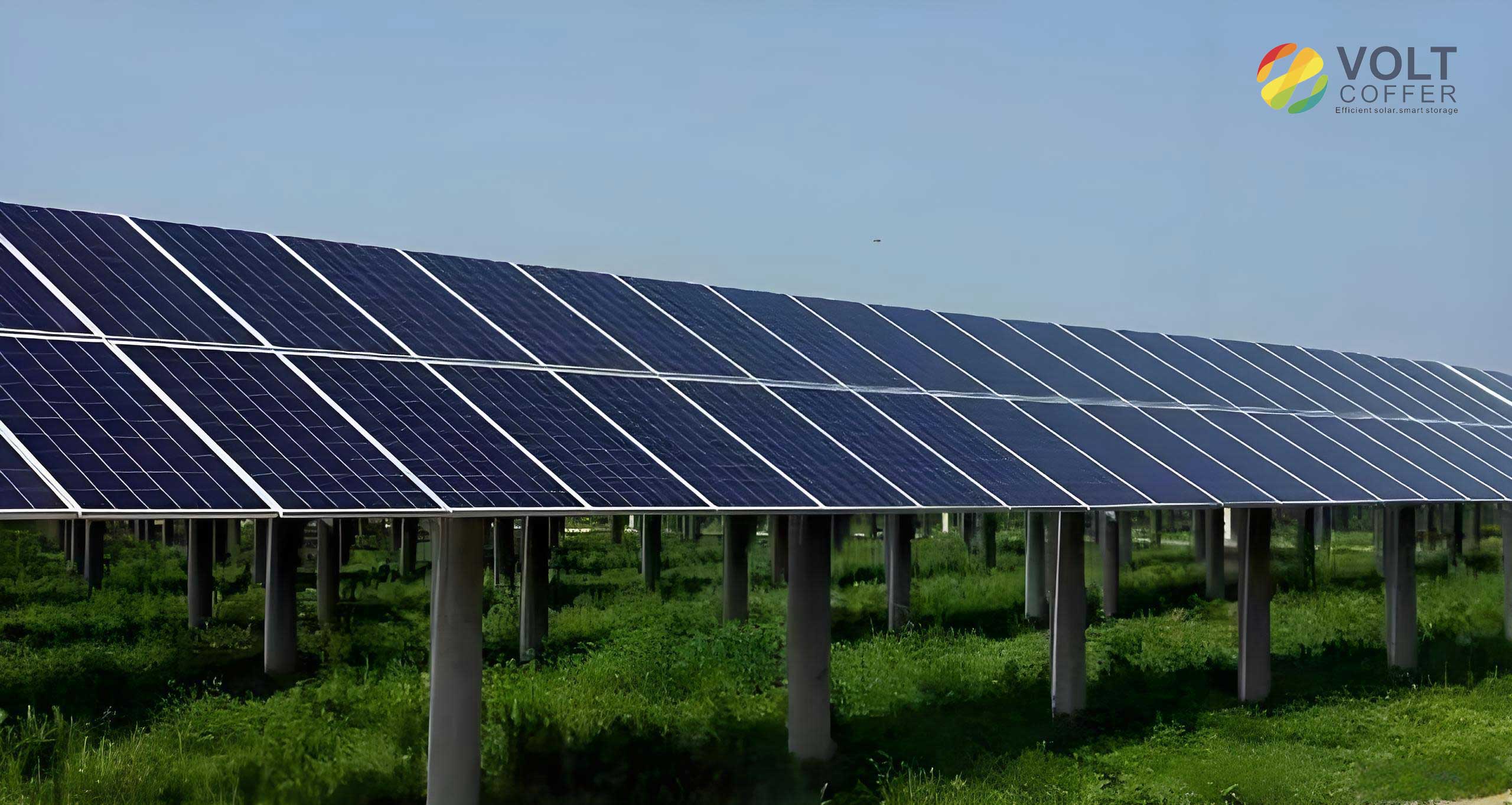
The core of the mechanical design is a dual-servo configuration. Two high-torque, waterproof servo motors (often referred to as rotary actuators) are employed. One servo is mounted vertically to control the azimuth angle (rotation around the vertical axis), while the second is mounted horizontally on the output of the first to control the elevation angle (tilt relative to the horizon). This arrangement provides two degrees of freedom essential for precise solar tracking. The use of servos is strategic; they integrate a DC motor, a gear train (often incorporating a worm gear for self-locking), and control circuitry into a sealed, robust package. The self-locking characteristic of the worm gear is pivotal—it allows the servo to hold its position without consuming any power once an adjustment is complete, eliminating the standby power drain common in other systems.
The structural design emphasizes simplicity and field robustness. The foundation can be a hollow structure filled with local material like sand or gravel on-site to minimize transport weight. A central steel pipe, which can also house control electronics, is anchored into this base. The azimuth servo is flange-mounted to the top of this pipe, ensuring a solid and aligned connection. The entire assembly for the solar panels is then attached to the output of the elevation servo. This modular and simple design reduces installation complexity and cost while improving durability against wind loads, especially when combined with intelligent stowing strategies.
The true innovation lies in the control paradigm. Instead of relying on local, error-prone light sensors, this system operates on commands received via a network data link. A central computational node, which could be a cloud server or a local control computer for a solar farm, calculates the optimal sun position for every panel’s specific geographic coordinates (latitude, longitude, altitude). This calculation uses precise astronomical algorithms, factoring in the time of day, day of the year, and other celestial parameters. The output is converted into precise Pulse Width Modulation (PWM) signals for each servo’s azimuth and elevation angles.
The system’s energy optimization strategy is dynamic. The tracking frequency is not constant. During early morning and late afternoon, when solar irradiance is low, the solar panels are adjusted less frequently with coarser steps to conserve the energy used for movement. Around solar noon, when irradiance is at its peak, the tracking becomes more frequent and precise, using the system’s finest resolution to capture every possible watt. This “smart tracking” algorithm maximizes the net energy gain.
The theoretical sun position is highly accurate, but real-world factors like installation misalignment and mechanical backlash can introduce errors. The network architecture allows for a closed-loop optimization process. Experimental units within a solar farm can be equipped with high-accuracy sensors. Their real-time performance data is fed back to the central node via the same network. This data is used to calibrate and refine the command signals, creating a system-specific feed-forward model that converges on an optimal solution. This hybrid approach marries the universality of theoretical models with the precision of empirical calibration.
| System Type | Energy Gain vs. Fixed | Control Method | Maintenance Need | Power Consumption |
|---|---|---|---|---|
| Fixed-Tilt Solar Panels | Baseline (0%) | None | Low | None |
| Single-Axis Tracker | ~15-25% | Active/Sensor-based | Medium | Medium |
| Dual-Axis Tracker (Traditional) | ~30-40% | Active/Sensor-based | High | High |
| Network-Controlled Dual-Axis | >35% (Estimated Net) | Network Command | Very Low | Very Low |
Mathematical Foundation for Solar Positioning and Control
The calculation of the sun’s position is based on well-established astronomical equations. The two critical angles for orienting solar panels are the solar azimuth angle ($\alpha_s$) and the solar zenith angle ($\theta_z$), the complement of the elevation angle ($\gamma_s$), where $\gamma_s = 90^{\circ} – \theta_z$.
First, several fundamental parameters need to be computed. The fractional year in radians ($\Gamma$) is given by:
$$ \Gamma = \frac{2\pi}{365} (d_n – 1 + \frac{h-12}{24}) $$
where $d_n$ is the day of the year, and $h$ is the hour in decimal UTC time.
The equation of time ($E_{time}$) in minutes and the solar declination angle ($\delta$) in radians are then approximated:
$$ E_{time} = 229.2 (0.000075 + 0.001868 \cos \Gamma – 0.032077 \sin \Gamma – 0.014615 \cos 2\Gamma – 0.04089 \sin 2\Gamma) $$
$$ \delta = 0.006918 – 0.399912 \cos \Gamma + 0.070257 \sin \Gamma – 0.006758 \cos 2\Gamma + 0.000907 \sin 2\Gamma – 0.002697 \cos 3\Gamma + 0.00148 \sin 3\Gamma $$
The true solar time ($T_{sol}$) is corrected for the observer’s longitude ($L_{long}$) and the equation of time:
$$ T_{sol} = h + \frac{L_{long}}{15} + \frac{E_{time}}{60} $$
The hour angle ($\omega$) in degrees is:
$$ \omega = 15 (T_{sol} – 12) $$
Finally, the solar zenith ($\theta_z$) and azimuth ($\alpha_s$) angles (in degrees) for an observer at latitude $\phi$ are:
$$ \cos \theta_z = \sin \phi \sin \delta + \cos \phi \cos \delta \cos \omega $$
$$ \gamma_s = 90^{\circ} – \theta_z $$
$$ \sin \alpha_s = \frac{-\cos \delta \sin \omega}{\sin \theta_z} \quad \text{or} \quad \cos \alpha_s = \frac{\sin \delta \cos \phi – \cos \delta \sin \phi \cos \omega}{\sin \theta_z} $$
Care must be taken to resolve the correct quadrant for $\alpha_s$ using the signs of both the sine and cosine components.
Control Signal Generation and Energy Yield Model
The central controller converts the calculated azimuth ($\alpha_{target}$) and elevation ($\gamma_{target}$) angles into servo-specific PWM duty cycle commands. For a standard 180-degree servo, the mapping is typically linear:
$$ PWM_{\text{duty, azimuth}} = PWM_{\text{min}} + \frac{(PWM_{\text{max}} – PWM_{\text{min}})}{180^\circ} \times \alpha_{target} $$
A similar equation holds for the elevation servo. Calibration offsets and scaling factors are applied to account for mechanical installation alignment and servo range limits.
The core benefit of tracking is the increased incident irradiance ($I_{tracked}$) on the solar panels compared to a fixed-tilt panel ($I_{fixed}$). The irradiance on a surface perpendicular to the sun’s rays is the direct normal irradiance (DNI). For a panel with surface normal vector $\hat{n}$, the effective irradiance is:
$$ I_{\text{effective}} = DNI \times (\hat{n} \cdot \hat{s}) + DHI $$
where $\hat{s}$ is the unit vector pointing to the sun, and DHI is the diffuse horizontal irradiance. For a perfectly tracked panel, $\hat{n} \cdot \hat{s} = 1$, maximizing the direct component capture. The energy yield ($E$) over a period T is the integral of power:
$$ E = A_{\text{panel}} \times \eta_{\text{PV}} \times \int_{T} I_{\text{effective}}(t) \, dt $$
where $A_{\text{panel}}$ is the area and $\eta_{\text{PV}}$ is the photovoltaic conversion efficiency. The energy gain from tracking is:
$$ \text{Gain} = \frac{E_{\text{tracked}} – E_{\text{fixed}}}{E_{\text{fixed}}} \times 100\% $$
Research indicates this gain can exceed 40% for dual-axis systems in clear-sky conditions. Our network-controlled system aims to maximize this gain while minimizing the parasitic energy consumption ($E_{drive}$) of the servos, leading to a superior net yield.
| Time of Day | Fixed Panel Yield (kWh/m²) | Dual-Axis Tracked Yield (kWh/m²) | Tracking Adjustment Frequency | Cumulative Gain |
|---|---|---|---|---|
| 8:00 – 10:00 | 0.45 | 0.68 | Low (30 min) | +51% |
| 10:00 – 12:00 | 0.95 | 1.32 | Medium (15 min) | +39% |
| 12:00 – 14:00 | 1.05 | 1.48 | High (5 min) | +41% |
| 14:00 – 16:00 | 0.80 | 1.10 | Medium (15 min) | +38% |
| 16:00 – 18:00 | 0.35 | 0.52 | Low (30 min) | +49% |
| Daily Total | 3.60 | 5.10 | Variable | +41.7% |
System Integration and Network Protocol
The integration of individual trackers into a solar farm network is crucial. Each dual-axis unit for the solar panels is equipped with a low-power microcontroller or network node capable of receiving data packets. The central server transmits compact data packets containing, at a minimum, the target angles or the raw PWM values for each servo. Lightweight communication protocols like MQTT or CoAP are ideal for this purpose due to their low overhead and suitability for IoT applications. The transmission interval varies according to the smart tracking algorithm—longer intervals during low-irradiance periods and shorter, more frequent updates during peak hours.
This architecture enables powerful fleet-management features. In case of impending severe weather, such as high winds or hail, the central server can broadcast an emergency command to all solar panels, instructing them to move to a predetermined stow position (e.g., face-down or edge-on to the wind) to minimize damage. This proactive protection, impossible with isolated sensor-based systems, significantly enhances the longevity and reliability of the entire installation. Furthermore, diagnostic data from each unit (e.g., operating temperature, movement cycles) can be reported back, facilitating predictive maintenance.
Advantages and Application Scope
The network-controlled dual-servo tracking system presents a compelling set of advantages for modern photovoltaic installations:
- High Reliability & Low Maintenance: The sealed servos and absence of exposed environmental sensors make the system highly resistant to dust, sand, and moisture, drastically reducing failure rates and maintenance costs.
- Energy-Efficient Operation: The self-locking mechanism and smart, variable-frequency tracking algorithm minimize the system’s own energy consumption, maximizing the net energy delivered to the grid.
- Superior Precision & Adaptability: Leveraging astronomical algorithms and network-fed calibration data ensures tracking precision that meets or exceeds the requirements of even high-concentration CPV systems. The control logic is software-based and can be updated or optimized remotely.
- Scalability and Smart Grid Integration: The system scales effortlessly from a single unit to a vast solar farm. Its network-native design allows for integration with broader smart grid management systems, enabling functions like coordinated reactive power support or output smoothing.
- Broad Applicability: While designed for standard photovoltaic solar panels, the same mechanical and control architecture can be applied to concentrating solar power (CSP) mirrors, solar furnaces, or daylighting systems by simply modifying the payload and refining the control parameters.
In conclusion, the shift from autonomous, sensor-based tracking to a centralized, network-commanded paradigm represents a significant advancement in solar tracking technology. By combining robust, self-locking servo actuators with intelligent, data-driven control delivered via a network data link, this system for solar panels achieves an optimal balance of high energy gain, exceptional reliability, and low operational cost. It provides a future-proof foundation for maximizing the return on investment in solar energy infrastructure across diverse environments and applications.