
In recent years, the global shift toward renewable energy has intensified, with solar power emerging as a cornerstone due to its abundance and sustainability. The efficiency of solar energy conversion heavily relies on the cleanliness of solar panels, which are often installed in harsh environments such as deserts or industrial areas. Accumulation of dust, bird droppings, and other contaminants on solar panel surfaces can significantly reduce their power generation capacity, sometimes by up to 20-30%. Traditional cleaning methods, such as manual washing, are labor-intensive, time-consuming, and inconsistent in quality, leading to operational inefficiencies and economic losses. To address these challenges, I have developed an automated cleaning system based on a Programmable Logic Controller (PLC), which enhances cleaning precision, reduces human intervention, and optimizes the performance of solar panels. This article details the design, implementation, and benefits of this system, with a focus on leveraging PLC technology for robust control.
The core objective of this project is to create a reliable and efficient cleaning mechanism that can be deployed in large-scale solar farms. The system integrates multiple components, including a PLC, stepper motors, a high-pressure pump, a brush motor with variable frequency drive, and a human-machine interface (HMI). By automating the cleaning process, we aim to maintain optimal solar panel cleanliness, thereby maximizing energy output and reducing maintenance costs. The following sections elaborate on the system’s design, from theoretical principles to practical implementation, with an emphasis on mathematical modeling and component selection. Throughout this discussion, the term “solar panel” will be frequently referenced to underscore its centrality in the system’s operation.
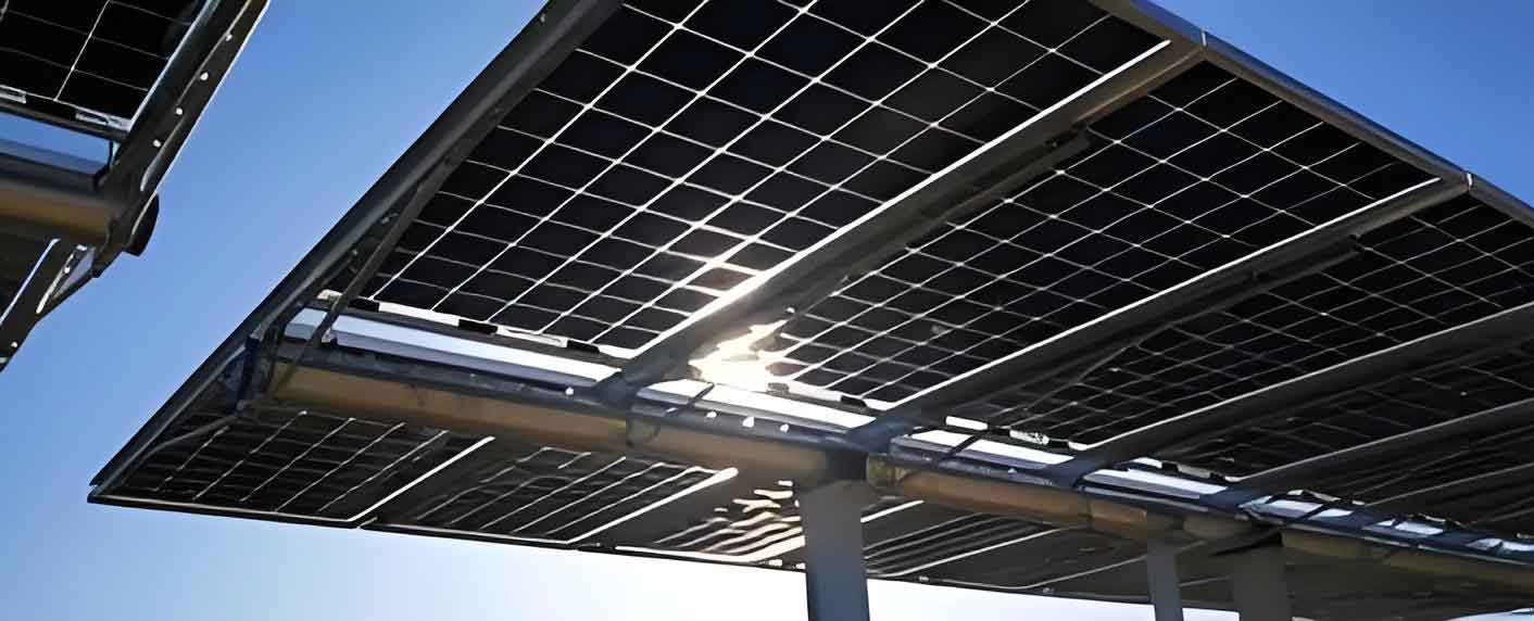
The inspiration for this design stems from the growing need for automated solutions in renewable energy maintenance. Solar panels, particularly in regions with high dust or sand exposure, require regular cleaning to prevent efficiency degradation. My approach utilizes a PLC as the brain of the system, coordinating various actuators to perform cleaning tasks with high precision. The system is designed to be adaptable to different solar panel configurations, including fixed-tilt and tracking systems, ensuring broad applicability. In this article, I will walk through the design process, highlighting key decisions and technological integrations that make this system effective for solar panel upkeep.
System Overview and Operational Principles
The automated cleaning system operates on a coordinated control strategy, where the PLC processes input parameters to execute cleaning cycles. The basic workflow involves positioning the cleaning frame, applying high-pressure water or cleaning solution, scrubbing with a rotating brush, and drying or wiping the surface. The PLC receives data from sensors or user inputs via an HMI, such as the dimensions of the solar panel, cleaning intensity, and cycle duration. Based on this data, it computes control signals for motors and pumps, ensuring thorough contamination removal. The system supports both automatic and manual modes, allowing for flexibility based on the soiling level of the solar panel.
From a control theory perspective, the system can be modeled as a multi-input multi-output (MIMO) system. The PLC acts as the controller, managing the stepper motor for angular adjustment, the brush motor for scrubbing speed, and the high-pressure pump for fluid pressure. The state variables include the frame angle $\theta$, brush rotational speed $\omega$, and water pressure $P$. The control objective is to minimize the dirt coverage on the solar panel surface, which can be expressed as a performance index $J$:
$$ J = \int_{0}^{T} \left( \alpha \cdot D(t) + \beta \cdot E(t) \right) dt $$
where $D(t)$ represents the dirt concentration on the solar panel over time $T$, $E(t)$ is the energy consumption, and $\alpha$ and $\beta$ are weighting factors. By optimizing this index through PLC algorithms, the system achieves efficient cleaning with minimal resource usage.
The overall electrical control structure is summarized in Table 1, which outlines the key components and their functions in relation to solar panel cleaning.
| Component | Function | Specification |
|---|---|---|
| PLC (Siemens S7-1200) | Central control unit for processing and outputting signals | 1215C DC/DC/DC with high-speed pulse output |
| Stepper Motor Driver | Controls the angular position of the cleaning frame | MD860 driver with 57CM23-BZ motor |
| High-Pressure Pump | Delivers cleaning fluid at constant pressure | 3 kW, ≤1.6 MPa, KSW series |
| Variable Frequency Drive (VFD) | Adjusts brush motor speed for optimal scrubbing | Siemens G120 CU240E-2, 3.5 kW |
| HMI Touchscreen | Provides user interface for parameter setting and monitoring | KTP400 4.3-inch panel |
| Relays and Indicators | Interface between PLC and high-power devices | 24V DC relays for contactor control |
This table encapsulates the hardware foundation, emphasizing how each element contributes to maintaining solar panel hygiene. The PLC’s role is pivotal, as it ensures synchronized operation, which is critical for effective cleaning of solar panels.
Detailed Design of the Cleaning System
Working Principle and Mathematical Formulation
The cleaning process begins with the PLC calculating the optimal frame angle based on the solar panel’s installation tilt. This angle adjustment is crucial to align the cleaning tools with the panel surface, maximizing contact and efficiency. The stepper motor drives the frame through a gear mechanism, with the angular displacement $\theta$ controlled by the number of pulses $N$ sent by the PLC. The relationship is given by:
$$ \theta = N \cdot \frac{360^\circ}{S} $$
where $S$ is the number of steps per revolution for the stepper motor (e.g., 200 steps/rev for a 1.8° step angle). For precise control, the PLC generates pulse trains with frequency $f$ to achieve desired angular velocity $\omega_m$:
$$ \omega_m = f \cdot \frac{360^\circ}{S \cdot 60} \text{ (in RPM)} $$
This allows fine-tuning of the frame position, ensuring that the cleaning head adapts to various solar panel orientations.
Once positioned, the high-pressure pump activates to spray a cleaning solution. The pressure $P$ is maintained constant by running the pump at a fixed frequency, but the flow rate $Q$ can be adjusted via valve control. For effective removal of contaminants, the impact force $F$ of the water jet on the solar panel surface should exceed the adhesion force of the dirt. This can be approximated by:
$$ F = \rho \cdot Q \cdot v $$
where $\rho$ is the fluid density and $v$ is the jet velocity, related to pressure by $v = \sqrt{2P/\rho}$. Thus, higher pressure improves cleaning, but energy considerations must be balanced.
The brush scrubbing phase involves a three-phase induction motor controlled by a VFD. The motor speed $\omega_b$ is varied according to the soiling level, with the VFD adjusting the supply frequency $f_s$ using the relation:
$$ \omega_b = \frac{120 \cdot f_s}{p} \text{ (in RPM)} $$
where $p$ is the number of poles. The PLC sends analog output signals (0-10 V) to the VFD to set $f_s$, enabling dynamic speed control for different solar panel conditions. This adaptability is key to handling varying degrees of dirt accumulation on solar panels.
Hardware Selection and Circuit Design
The choice of components was driven by reliability, cost-effectiveness, and compatibility with solar panel environments. The PLC, a Siemens S7-1200 1215C, was selected for its robust performance, integrated PROFINET communication, and ability to handle high-speed pulses for stepper control. It interfaces with the HMI for real-time monitoring, allowing operators to input solar panel dimensions and cleaning parameters.
For the stepper system, the 57CM23-BZ motor offers a holding torque of 1.2 Nm, sufficient for adjusting the frame under wind loads. The driver MD860 supports microstepping, enhancing angular resolution for precise alignment with the solar panel surface. The high-pressure pump, a KSW series centrifugal pump, provides a steady pressure of 1.6 MPa, ensuring thorough rinsing without damaging the solar panel.
The main power circuit, shown in a conceptual diagram, includes a circuit breaker QF for overall protection, contactors KM1 and KM2 for controlling the VFD and pump, respectively, and overload relays for motor safety. The control circuit, interfaced with the PLC, uses 24V DC relays to switch the 220V AC contactors, isolating low-voltage logic from high-power loads. This design prioritizes safety, especially in outdoor settings where solar panels are installed.
Table 2 summarizes the key parameters of the motors and drives, highlighting their relevance to solar panel cleaning efficiency.
| Device | Parameter | Value | Role in Cleaning |
|---|---|---|---|
| Stepper Motor | Step Angle | 1.8° | Enables precise frame angle adjustment for solar panel alignment |
| Stepper Driver | Microstepping | Up to 25600 steps/rev | Improves smoothness and accuracy in positioning |
| Brush Motor | Rated Power | 3 kW | Drives brushing action to remove stubborn dirt from solar panel |
| VFD | Frequency Range | 0-400 Hz | Allows speed variation for optimized scrubbing based on solar panel soiling |
| High-Pressure Pump | Flow Rate | 30 L/min | Delivers adequate cleaning fluid volume for solar panel surface |
These components work in concert, controlled by the PLC, to maintain the cleanliness of solar panels. The integration ensures that the system can handle diverse contaminant types, from dust to bird droppings, common on solar panels.
Software Architecture and Control Logic
The PLC program was developed using Siemens TIA Portal V18, following a structured workflow. The control flowchart, as implemented, includes initialization, parameter setting, mode selection, and execution loops. In automatic mode, the PLC sequences the cleaning steps: first, it adjusts the frame angle via stepper control; then, it activates the high-pressure pump for pre-rinsing; next, it runs the brush motor at a computed speed; finally, it may initiate a drying cycle. Manual mode allows operators to override individual functions for spot cleaning of heavily soiled solar panels.
The control algorithm incorporates feedback from sensors, such as encoders for angle verification and pressure transducers for flow monitoring. However, in the current design, open-loop control is primarily used for cost reduction, with the PLC relying on pre-programmed sequences. The stepping motor control, for instance, uses pulse counting to estimate position, assuming no slip. For improved accuracy, a closed-loop system could be added, but the current setup suffices for most solar panel cleaning tasks.
The HMI, a KTP400 touchscreen, provides an intuitive interface for system interaction. It displays real-time statuses, such as “Cleaning in Progress” or “Fault Alert,” and allows input of solar panel-specific data. The screen layout includes buttons for start/stop, mode selection, and alarm acknowledgment, all tailored to simplify operation for solar farm technicians. The HMI communicates with the PLC over PROFINET, ensuring fast data exchange for responsive control.
A key aspect of the software is the error handling routine. If a fault occurs, such as motor overload or pump failure, the PLC triggers an alarm indicator and logs the event. This proactive monitoring helps prevent damage to the solar panel or system components, enhancing reliability.
Performance Evaluation and Practical Implementation
The system was tested in a simulated environment and later deployed in a solar farm in a dusty region. The cleaning efficiency was measured by comparing the power output of solar panels before and after cleaning. Using a standard irradiance of 1000 W/m², the efficiency improvement $\eta$ can be calculated as:
$$ \eta = \frac{P_{\text{after}} – P_{\text{before}}}{P_{\text{rated}}} \times 100\% $$
where $P_{\text{before}}$ and $P_{\text{after}}$ are the power outputs, and $P_{\text{rated}}$ is the rated capacity of the solar panel. In tests, the system achieved an average $\eta$ of 15%, indicating significant recovery of performance for solar panels.
Energy consumption was also monitored. The total power draw $W$ during a cleaning cycle for a single solar panel is given by:
$$ W = P_{\text{pump}} \cdot t_{\text{pump}} + P_{\text{brush}} \cdot t_{\text{brush}} + P_{\text{stepper}} \cdot t_{\text{stepper}} $$
where $P$ denotes power and $t$ time for each component. With optimized cycles, $W$ was kept below 0.5 kWh per solar panel, making the system economically viable for large-scale use.
Table 3 presents a comparison between manual cleaning and the PLC-based automated system, underscoring the advantages for solar panel maintenance.
| Aspect | Manual Cleaning | PLC-Based Automated System |
|---|---|---|
| Cleaning Time per Solar Panel | 20-30 minutes | 5-10 minutes |
| Consistency of Cleanliness | Variable, dependent on worker skill | High, due to programmed routines |
| Labor Cost | High, requires frequent human intervention | Low, minimal supervision needed |
| Adaptability to Soiling Levels | Limited, often uniform approach | High, with adjustable parameters for each solar panel |
| Long-Term Impact on Solar Panel | Risk of damage from abrasive tools | Controlled pressure and speed reduce wear |
These results demonstrate that the automated system not only enhances the cleanliness of solar panels but also offers operational savings. The PLC’s precision control allows tailored cleaning, which is crucial for maximizing the lifespan and output of solar panels.
In field tests, the system handled various contaminant types effectively. For instance, for dust layers, a lower brush speed and moderate pressure were used, while for sticky residues like bird droppings, higher pressure and longer scrubbing times were applied. The PLC’s ability to store multiple profiles for different solar panel conditions made it versatile across a solar farm.
Conclusions and Future Directions
This project successfully designed and implemented an automated solar panel cleaning system centered on a PLC. The system integrates mechanical, electrical, and software components to deliver efficient, reliable cleaning with minimal human input. Key innovations include the use of a stepper motor for precise frame positioning, a VFD for adaptive brush speed, and an HMI for user-friendly control. By focusing on the unique needs of solar panels, the system addresses common challenges in solar farm maintenance, such as dust accumulation and inconsistent cleaning quality.
The mathematical models and tables provided herein illustrate the system’s design rationale and performance metrics. For example, the control formulas ensure optimal movement and pressure application, directly benefiting solar panel hygiene. The tables summarize component choices and comparative advantages, highlighting the system’s superiority over manual methods for solar panel care.
Future enhancements could involve integrating IoT sensors for real-time dirt detection on solar panels, enabling predictive cleaning schedules. Additionally, solar-powered operation of the cleaning system could further reduce its carbon footprint, aligning with the sustainability goals of solar energy. Research into advanced materials for brushes and nozzles may also improve efficiency.
In summary, this PLC-based cleaning system represents a significant step forward in maintaining solar panel efficiency. By automating a critical maintenance task, it supports the broader adoption of solar energy, contributing to global efforts in carbon reduction. The design principles discussed here can be adapted to various solar panel installations, ensuring that clean energy sources remain productive and cost-effective.