
The pursuit of sustainable transportation has intensified the search for efficient, on-board renewable energy solutions. Among these, integrating solar panels onto vehicles presents a promising avenue for extending range and reducing dependency on grid charging. However, traditional implementations face significant limitations due to spatial constraints on vehicle rooftops. A fixed, single-layer solar panel offers limited surface area, which directly caps its energy harvesting potential. This fundamental mismatch between the available space and the desired energy output has been a persistent bottleneck. My design addresses this core issue through a novel, deployable architecture: the Drawer-Type Multi-Layer Solar Panel System. This system reimagines the vehicle-integrated solar panel not as a static component, but as a dynamic, scalable energy-capturing surface that can adapt to parking conditions and energy needs.
The conventional approach involves permanently mounting a single solar panel on the vehicle’s roof. The total energy, \( E_{\text{single}} \), collected over a period is governed by the formula:
$$ E_{\text{single}} = A_{\text{roof}} \cdot \eta_{\text{panel}} \cdot G \cdot t $$
where \( A_{\text{roof}} \) is the fixed roof area, \( \eta_{\text{panel}} \) is the solar panel’s conversion efficiency, \( G \) is the solar irradiance, and \( t \) is the exposure time. The clear limitation is that \( A_{\text{roof}} \) is a small, constant value, leading to insufficient charging rates for practical vehicle support. My design philosophy breaks this constraint by introducing a variable effective area, \( A_{\text{effective}} \), which can be greater than \( A_{\text{roof}} \).
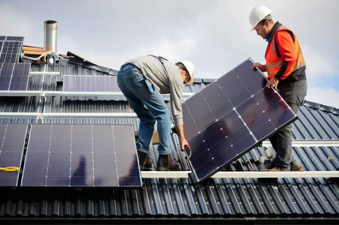
The core innovation is a master-slave panel configuration with a mechanized deployment system. The primary master solar panel is fixed onto the vehicle’s roof, serving as the base unit and housing. Integrated within its structure are three secondary, or “slave,” solar panels. These secondary solar panels are mounted on robust, low-friction slide mechanisms, allowing them to be stored completely within the footprint of the master solar panel or deployed outward horizontally when the vehicle is stationary. This drawer-like operation is the namesake of the design.
The system’s operational matrix and key comparative advantages are summarized below:
| Feature | Traditional Single Panel | Drawer-Type Multi-Layer System |
|---|---|---|
| Deployable Area | Fixed (A_roof) | Variable, up to ~4 x A_roof |
| Energy Harvest Potential | \( E_{\text{single}} = A_{\text{roof}} \cdot \eta \cdot G \cdot t \) | \( E_{\text{multi}} = n \cdot A_{\text{panel}} \cdot \eta \cdot G \cdot t \) (n=1 to 4) |
| Aerodynamic Impact | Minimal (fixed profile) | Minimal when retracted; manageable drag when deployed stationary. |
| Spatial Efficiency | Low (uses only roof plane) | High (utilizes 3D space around vehicle when parked) |
| Adaptability | None | High. Can deploy 1, 2, 3, or 4 panels based on space/parking alignment. |
| Structural Complexity | Low | Moderate (requires housing, slides, and locking mechanisms) |
Let’s delve into the detailed configuration. The system is a four-layer structure in its fully deployed state. Layer 1 is the Master Solar Panel, permanently attached. Layers 2, 3, and 4 are the Slave Solar Panels—Slave 1, Slave 2, and Slave 3, respectively. They are housed in dedicated compartments within the master panel’s frame, aligned to deploy in specific directions: typically to the right, left, and rear of the vehicle. This tri-directional deployment maximizes area expansion while considering typical parking layouts and minimizing shadow casting between the deployed solar panels.
The energy yield enhancement is not merely additive but multiplicative in terms of surface area. If each individual solar panel, whether master or slave, has an area \( A_p \) and efficiency \( \eta \), the total energy for a fully deployed system in ideal, unshaded conditions is:
$$ E_{\text{total}} = 4 \cdot (A_p \cdot \eta \cdot G \cdot t) = 4 \cdot E_{\text{single\_panel}} $$
This represents a 300% increase in potential energy capture compared to using only the master solar panel area. The practical gain depends on the “Extension Factor,” \( F_e \), defined as the ratio of deployed area to retracted area. For this design:
$$ F_e = \frac{A_{\text{master}} + \sum_{i=1}^{3} A_{\text{slave}_i}}{A_{\text{master}}} = \frac{4A_p}{A_p} = 4 $$
The deployment mechanism must be robust, weather-sealed, and low-power. A motorized lead-screw or rack-and-pinion system integrated into each slide channel is proposed. The control logic is simple: upon vehicle parking and engaging a “Solar Charge Mode,” the system can automatically deploy all available slave solar panels, or the user can select the number via a vehicle interface based on parking space constraints. Limit switches ensure full extension/retraction, and mechanical locks secure the panels in both states to prevent rattling during transit or movement in wind.
A critical engineering challenge is managing the electrical integration of these multiple, moving solar panels. A centralized Maximum Power Point Tracking (MPPT) charge controller is optimal. The output from all four solar panels—the master solar panel and the three slave solar panels—is connected in parallel through the sliding interfaces (using flexible cable loops or conductive brush contacts) to the MPPT controller. This configuration ensures that even if one deployed solar panel is partially shaded, it does not disproportionately drag down the performance of the entire array, as it might in a series connection. The total current \( I_{\text{total}} \) into the battery is:
$$ I_{\text{total}} = I_{\text{master}} + I_{\text{slave1}} + I_{\text{slave2}} + I_{\text{slave3}} $$
where each current \( I_x \) is determined by the MPPT controller optimizing the power \( P_x = V_x \cdot I_x \) for each panel or string. The system’s wiring diagram is conceptually straightforward but requires careful design for durability at movement points.
The material selection for the housing and slides is crucial for longevity and weight. The enclosure for the master solar panel must be rigid, lightweight, and waterproof. Aluminum alloys are prime candidates. The slide mechanisms require materials with excellent wear resistance and low friction coefficients, such as anodized aluminum rails with polymer composite bearings. The total system weight, \( W_{\text{system}} \), can be approximated as:
$$ W_{\text{system}} = W_{\text{master\_module}} + 3 \cdot (W_{\text{slave\_panel}} + W_{\text{slide\_assembly}}) $$
where \( W_{\text{master\_module}} \) includes the master solar panel, its robust housing, and the integrated compartments. This added mass must be factored into the vehicle’s overall weight and center of gravity calculations, though the impact is minor relative to the mass of the battery pack.
The benefits of this multi-layer solar panel system extend beyond simple energy arithmetic. First, it decouples the vehicle’s energy-harvesting capability from its roof area. A small city car can now have the solar charging potential of a much larger vehicle when parked. Second, it offers adaptability. In a tight parking space, only the master solar panel may be active. In an open field or dedicated charging spot, all four solar panels can be deployed. Third, it enhances redundancy. If one slave solar panel fails, the others remain operational.
To quantify the practical impact, consider a typical scenario with a solar irradiance \( G = 800 \, \text{W/m}^2 \) and a panel efficiency \( \eta = 0.22 \). For a single solar panel of area \( A_p = 1.5 \, \text{m}^2 \), the peak power is:
$$ P_{\text{single}} = 1.5 \, \text{m}^2 \cdot 0.22 \cdot 800 \, \text{W/m}^2 = 264 \, \text{W} $$
For the fully deployed four-panel system:
$$ P_{\text{multi}} = 4 \cdot 264 \, \text{W} = 1056 \, \text{W} $$
Over a 5-hour sun exposure period, the energy yield difference is substantial:
| Configuration | Peak Power (W) | Energy per 5h (kWh) | Potential Range Extension* (km) |
|---|---|---|---|
| Single Panel | 264 | 1.32 | ~6-8 km |
| Fully Deployed System | 1056 | 5.28 | ~24-32 km |
*Assuming 6.5 km/kWh consumption, a common efficiency for compact EVs.
This daily range extension can significantly reduce the frequency of grid charging, effectively turning a vehicle into a more self-sufficient entity. The psychological and practical benefit of “free” daily mileage is a powerful advantage for consumer adoption.
The design also opens avenues for smart features. With integrated light sensors on each face of the master solar panel housing, the system could intelligently decide which slave solar panels to deploy based on the sun’s azimuth and surrounding obstructions. For instance, if the vehicle is parked against a wall on its left side, only the master, right, and rear solar panels would be deployed. The control logic would maximize the total irradiance capture, defined as:
$$ G_{\text{total\_capture}} = \sum_{i=1}^{4} (G_i \cdot A_i \cdot \cos(\theta_i)) $$
where \( G_i \) is the irradiance on the i-th panel’s surface, \( A_i \) is its area, and \( \theta_i \) is the angle of incidence of sunlight on that panel. The system would solve for the deployment combination that maximizes this sum, given binary (deployed/retracted) states for the slave panels.
From a broader technological perspective, this drawer-type multi-layer solar panel concept represents a shift from passive to active vehicle-integrated photovoltaics (VIPV). It addresses the core density problem of solar energy on small mobile platforms. While the concept is presented for passenger electric vehicles, its applications are vast: recreational vehicles (RVs), delivery vans, buses, and even specialized military or exploration vehicles that operate in remote areas. For an RV, this system could dramatically extend boondocking capability. For a delivery van parked for hours between routes, it could provide essential power for refrigeration units or onboard systems without idling an engine.
In conclusion, the limitations of fixed, single-layer solar panels on vehicles are fundamentally tied to immutable surface area. My proposed Drawer-Type Multi-Layer Solar Panel System innovates by transforming the solar panel from a static surface into a scalable, deployable energy-harvesting system. By housing secondary solar panels within a primary unit and deploying them mechanically when needed, it decouples energy potential from vehicle footprint. This design significantly increases the effective area of the solar panel array, leading to a proportional increase in energy yield and practical vehicle range extension. The integration of robust mechanics, smart electrical management, and adaptive control logic makes this not just a concept, but a feasible path forward for enhancing the sustainability and utility of electric mobility. The future of vehicle-integrated solar lies in such dynamic, intelligent systems that maximize resource capture within our spatial realities.