
The proliferation of large-scale solar power plants has presented a significant operational challenge: the efficient and cost-effective cleaning of solar panel arrays. Accumulation of dust, dirt, and other particulates on the panel surface drastically reduces photovoltaic conversion efficiency, leading to substantial energy yield losses. Traditional manual cleaning methods are labor-intensive, hazardous, time-consuming, and economically unsustainable for vast solar farms. Consequently, the development of automated cleaning solutions, specifically robotic systems, has become a critical research and engineering focus. A key to the precise and reliable operation of such a robotic cleaner is the accurate kinematic modeling of its manipulator arm, which governs the motion and positioning of the cleaning end-effector across the solar panel surface.
This article presents a comprehensive kinematic analysis of a solar panel cleaning robot’s arm mechanism. The primary objective is to establish a precise mathematical model that describes the mapping between the robot’s actuator inputs, its joint configurations, and the position and orientation (pose) of its cleaning head relative to the solar panel. We adopt the Denavit-Hartenberg (D-H) convention, a standard method in robotics, to systematically model the serial-chain linkage of the manipulator. The kinematics problem is decomposed into mappings between three distinct spaces: the actuator space (hydraulic cylinder lengths/motor angles), the joint space (link angles), and the task-space or pose-space (end-effector coordinates and orientation). Detailed derivations for both forward and inverse kinematics are provided. Furthermore, the model is implemented and validated through simulation in MATLAB, with a particular analysis of the robot’s workspace to verify its capability to cover standard solar panel dimensions. The derived model serves as the foundational theory for subsequent trajectory planning, dynamic analysis, and real-time motion control algorithms essential for autonomous solar panel maintenance.
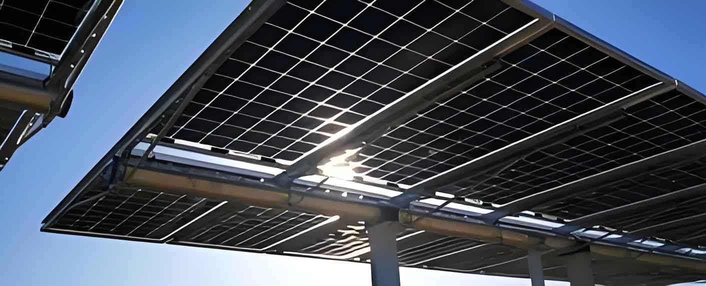
The robotic system under study consists of a mobile base and a multi-degree-of-freedom manipulator arm. The base, often tracked or wheeled, provides gross translation along the aisle between rows of solar panels. The manipulator arm, mounted on this base, is responsible for the precise deployment and motion of the cleaning tool (e.g., brush, spray nozzle, vacuum head) across the panel surface. For the purpose of kinematic analysis, we isolate the manipulator arm, treating it as a serial robotic chain. The arm typically comprises a rotational base joint, followed by several links actuated by linear hydraulic cylinders or rotary motors, culminating in an end-effector that may also have its own orientation control. Accurately modeling this chain is paramount for ensuring the cleaning tool follows a desired path on the solar panel while maintaining appropriate contact and orientation.
The core challenge is to define the mathematical relationship between the controlled actuator displacements and the resulting end-effector pose. We define the following spaces:
- Actuator Space (A): Defined by the set of controlled actuator variables. For a hydraulic arm, these are typically the lengths of hydraulic cylinders $l_i$. A rotary base joint is controlled by an angle $\theta_1$.
- Joint Space (Q): Defined by the set of joint variables that describe the relative configuration of adjacent links. For revolute joints, this is the joint angle $\theta_i$; for prismatic joints, it is the joint displacement $d_i$. The geometry of the linkage defines the mapping $A \rightarrow Q$.
- Pose Space (W): Defined by the position $(x, y, z)$ and orientation (often represented by angles like $\phi, \theta, \psi$ or a rotation matrix) of the end-effector in a fixed world or base coordinate frame. The kinematic model defines the mapping $Q \rightarrow W$.
The forward kinematics problem is to find $W$ given $Q$. The inverse kinematics problem is to find $Q$ (and consequently $A$) given a desired $W$. For effective control of the solar panel cleaning robot, we must understand all these mappings: $A \leftrightarrow Q \leftrightarrow W$.
Kinematic Modeling Using the Denavit-Hartenberg Convention
The D-H convention provides a systematic method to assign coordinate frames to each link of a serial robot and to derive the homogeneous transformation matrix between consecutive frames. For our solar panel cleaning robot arm, we simplify the mechanical structure into an equivalent kinematic diagram of connected links and joints. A base coordinate frame $\{0\}$ is fixed to the robot’s turning platform. A frame $\{i\}$ is attached to link $i$, for $i = 1$ to $n$, where $n$ is the number of joints. The D-H parameters for link $i$ are defined by four values:
- $\theta_i$: The joint angle (for a revolute joint) about the $z_{i-1}$-axis.
- $d_i$: The link offset along the $z_{i-1}$-axis.
- $a_i$: The link length (distance along the $x_i$-axis from $z_{i-1}$ to $z_i$).
- $\alpha_i$: The link twist (angle about the $x_i$-axis from $z_{i-1}$ to $z_i$).
The homogeneous transformation matrix $^{i-1}\mathbf{T}_i$, which transforms coordinates from frame $\{i\}$ to frame $\{i-1\}$, is given by:
$$^{i-1}\mathbf{T}_i = \begin{bmatrix}
\cos\theta_i & -\sin\theta_i \cos\alpha_i & \sin\theta_i \sin\alpha_i & a_i \cos\theta_i \\
\sin\theta_i & \cos\theta_i \cos\alpha_i & -\cos\theta_i \sin\alpha_i & a_i \sin\theta_i \\
0 & \sin\alpha_i & \cos\alpha_i & d_i \\
0 & 0 & 0 & 1
\end{bmatrix}$$
The complete forward kinematics from the base frame $\{0\}$ to the end-effector frame $\{n\}$ is found by concatenating these transformations:
$$^{0}\mathbf{T}_{n} = ^{0}\mathbf{T}_{1} \cdot ^{1}\mathbf{T}_{2} \cdot … \cdot ^{n-1}\mathbf{T}_{n}$$
The position and orientation of the end-effector are extracted from the matrix $^{0}\mathbf{T}_{n}$.
D-H Parameter Assignment for the Solar Panel Cleaner Arm
The specific solar panel cleaning robot arm analyzed here features a five-degree-of-freedom serial chain: a rotary base and three main arm segments actuated by hydraulic cylinders, plus a final orientation joint for the cleaning head. The corresponding kinematic diagram and assigned D-H frames are conceptualized as follows: Frame $\{0\}$ is at the base rotation center. Frame $\{1\}$ is attached after the base rotation $\theta_1$. Frames $\{2\}$, $\{3\}$, and $\{4\}$ are attached to the subsequent arm links, with their joint angles $\theta_2, \theta_3, \theta_4$ being functions of the hydraulic cylinder extensions. Frame $\{5\}$ is at the cleaning head, with $\theta_5$ controlling its orientation relative to the solar panel surface.
Based on the mechanical design and geometry, the D-H parameters are summarized in the table below. Note that $\theta_2, \theta_3, \theta_4$ are the joint variables for the arm links, not the cylinder lengths themselves. The mapping from cylinder length to these joint angles is derived separately.
| Link $i$ | $\theta_i$ (Joint Var.) | $\alpha_i$ (Twist) | $a_i$ (Length) | $d_i$ (Offset) |
|---|---|---|---|---|
| 1 | $\theta_1$ | 90° | $a_1$ | $d_1$ |
| 2 | $\theta_2$ | 0° | $a_2$ | 0 |
| 3 | $\theta_3$ | 0° | 0 | $d_3$ |
| 4 | $\theta_4$ | 90° | 0 | 0 |
| 5 | $\theta_5$ | 90° | $a_4$ | $d_4$ |
Where $a_1, a_2, a_4, d_1, d_3, d_4$ are constant geometric lengths specific to the robot’s design.
Forward Kinematics: Joint Space to Pose Space
Using the D-H parameters from the table, we compute the transformation matrices for each link. For brevity, we use the shorthand $c_i = \cos\theta_i$, $s_i = \sin\theta_i$, $c_{ij} = \cos(\theta_i+\theta_j)$, $s_{ij} = \sin(\theta_i+\theta_j)$.
$$^{0}\mathbf{T}_{5} = ^{0}\mathbf{T}_{1} \cdot ^{1}\mathbf{T}_{2} \cdot ^{2}\mathbf{T}_{3} \cdot ^{3}\mathbf{T}_{4} \cdot ^{4}\mathbf{T}_{5}$$
After performing the matrix multiplications, the overall transformation matrix is obtained. The position of the end-effector origin (the cleaning head) in base coordinates $\{0\}$ is given by the first three elements of the fourth column of $^{0}\mathbf{T}_{5}$:
$$^{0}\mathbf{P}_{5} = \begin{bmatrix} x \\ y \\ z \end{bmatrix} =
\begin{bmatrix}
c_1(a_1 + a_2 c_2 + d_3 c_{23} + a_4 c_{234}) + d_4 s_1 \\
s_1(a_1 + a_2 c_2 + d_3 c_{23} + a_4 c_{234}) – d_4 c_1 \\
a_2 s_2 + d_3 s_{23} + a_4 s_{234} + d_1
\end{bmatrix}$$
Where $\theta_{234} = \theta_2 + \theta_3 + \theta_4$. The orientation of the end-effector is encapsulated in the $3 \times 3$ rotation sub-matrix of $^{0}\mathbf{T}_{5}$. For the task of cleaning a solar panel, a critical orientation parameter is the angle of the cleaning head relative to the panel normal. If we define a simplified orientation variable $\phi$ representing the angle of the last link (and thus the cleaning tool) relative to the horizontal (or the solar panel plane), it can be expressed as a function of the joint angles. In this model, $\phi$ is primarily governed by $\theta_5$ but is also influenced by the orientation of link 4. For a basic analysis focusing on reachability, we often consider the “direction” of the last arm segment, which is $\theta_{234}$. Therefore, the complete pose vector for workspace analysis can be defined as $\mathbf{W} = [x, y, z, \theta_{234}]^T$. The forward kinematics mapping $f: \mathbf{Q} \rightarrow \mathbf{W}$ is thus:
$$\mathbf{W} = \begin{bmatrix}
c_1(a_1 + a_2 c_2 + d_3 c_{23} + a_4 c_{234}) + d_4 s_1 \\
s_1(a_1 + a_2 c_2 + d_3 c_{23} + a_4 c_{234}) – d_4 c_1 \\
a_2 s_2 + d_3 s_{23} + a_4 s_{234} + d_1 \\
\theta_2 + \theta_3 + \theta_4
\end{bmatrix}$$
This equation allows us to compute the cleaning head’s position and approach angle for any given set of joint angles $\theta_1$ through $\theta_4$.
Inverse Kinematics: Pose Space to Joint Space
Solving the inverse kinematics (IK) is necessary to find the required joint angles to place the cleaning head at a desired position and orientation on the solar panel. Given the structure of the manipulator, a geometric approach is effective. We are given a desired end-effector pose $\mathbf{W_d} = [x_d, y_d, z_d, \phi_d]^T$, where $\phi_d = \theta_{2,d} + \theta_{3,d} + \theta_{4,d}$.
First, solve for the base rotation $\theta_1$. From the forward kinematics equations for $x$ and $y$, we can isolate terms involving $\theta_1$. A common method involves manipulating the equations to find:
$$\theta_1 = \text{atan2}(y_d, x_d) \pm \delta$$
Where $\delta$ comes from considering the offset $d_4$. A more precise derivation involves solving the equations $x’ = x_d – d_4 s_1$ and $y’ = y_d + d_4 c_1$, which represent a point on the axis of the final joint. From these, one can derive $\theta_1 = \text{atan2}(y’, x’)$ or solve using the tangent half-angle formula.
Once $\theta_1$ is known, the problem reduces to solving for $\theta_2, \theta_3, \theta_4$ from the desired wrist position $(x’_w, y’_w, z’_w)$ and the orientation constraint $\phi_d$. The wrist position is the point where the last three joint axes intersect (simplified model). We define:
$$x’_w = x_d – a_4 c_1 c_{\phi_d} – d_4 s_1$$
$$y’_w = y_d – a_4 s_1 c_{\phi_d} + d_4 c_1$$
$$z’_w = z_d – a_4 s_{\phi_d} – d_1$$
Let $R = \sqrt{(x’_w – a_1 c_1)^2 + (y’_w – a_1 s_1)^2}$ and $D = z’_w$. This is now a 2D problem in the plane of the arm. Using the Law of Cosines on the triangle formed by links of length $a_2$, $d_3$, and the line from joint 2 to the wrist, we can solve for $\theta_3$:
$$L = \sqrt{R^2 + D^2}$$
$$\theta_3 = \pm \arccos\left( \frac{L^2 – a_2^2 – d_3^2}{2 a_2 d_3} \right)$$
The $\pm$ sign corresponds to elbow-up and elbow-down configurations. Next, we solve for $\theta_2$:
$$\theta_2 = \text{atan2}(D, R) – \arctan\left( \frac{d_3 s_3}{a_2 + d_3 c_3} \right)$$
Finally, $\theta_4$ is determined from the orientation constraint:
$$\theta_4 = \phi_d – \theta_2 – \theta_3$$
This geometric solution provides the necessary joint angles to achieve a target cleaning point and tool angle on the solar panel.
Actuator Space to Joint Space Mapping
The solar panel cleaning robot uses hydraulic cylinders to actuate the main arm links. Therefore, the joint angles $\theta_2, \theta_3, \theta_4$ are not directly controlled but are functions of the corresponding cylinder lengths $l_2, l_3, l_4$. This mapping is derived from the specific geometry of the four-bar linkage or linear-actuated rocker arm mechanisms that constitute each joint.
Consider a typical joint $i$ (for $i=2,3,4$) where a hydraulic cylinder of variable length $l_i$ is attached between two points $\mathbf{A}_i$ and $\mathbf{B}_i$ on the parent and child links, respectively. Let the fixed geometric parameters be: the coordinates of the attachment points in their local link frames, and the fixed pivot points of the links. The relationship is found using the law of cosines in the triangle formed by the cylinder and the two link segments.
For example, for joint 2, let the fixed pivot on link 1 be point $C$, the pivot on link 2 be point $B$, and the cylinder attachment points be $A$ (on link 1) and $D$ (on link 2). The cylinder length is $l_2 = ||\vec{AD}||$. Knowing the fixed distances $||\vec{AC}||$, $||\vec{CB}||$, $||\vec{BD}||$, and the angle $\angle ACB$ as a constant $\gamma$, we can express $\theta_2$ as:
$$l_2 = \sqrt{||\vec{AC}||^2 + ||\vec{CB}||^2 – 2 ||\vec{AC}|| ||\vec{CB}|| \cos(\angle ACB)}$$
Where $\angle ACB = \gamma + \theta_2’$ (where $\theta_2’$ is an offset angle related to $\theta_2$). Therefore,
$$\theta_2 = \arccos\left( \frac{||\vec{AC}||^2 + ||\vec{CB}||^2 – l_2^2}{2 ||\vec{AC}|| ||\vec{CB}||} \right) – \gamma$$
Similar geometric relationships are established for $\theta_3 = g_3(l_3)$ and $\theta_4 = g_4(l_4)$. The base joint $\theta_1$ is typically directly driven by a hydraulic motor, so $\theta_1$ is proportional to the motor’s angular displacement. These mappings $g_i$ complete the full kinematic chain from actuator commands $(l_2, l_3, l_4, \theta_1, \theta_5)$ to the end-effector pose $[x, y, z, \phi]$. Accurate calibration of these geometric constants is crucial for the precise positioning of the solar panel cleaning head.
Simulation and Workspace Analysis
To validate the derived kinematic model and analyze the operational capabilities of the solar panel cleaning robot, a simulation was developed in MATLAB. The physical dimensions of the manipulator were based on a representative design: $a_1 = 0.5144 \text{ m}$, $a_2 = 2.1754 \text{ m}$, $d_3 = 2.2411 \text{ m}$, $a_4 = 0.4821 \text{ m}$, $d_1 = 0.3976 \text{ m}$, $d_4 = 0.3752 \text{ m}$.
The forward kinematics function was implemented according to the equation for $\mathbf{W}$. To test the consistency of the model, an inverse kinematics solver based on the geometric method was also implemented. A test trajectory was defined by specifying a time-varying set of joint angles (simulating actuator movements), and the forward kinematics computed the corresponding end-effector trajectory. This end-effector trajectory was then fed into the inverse kinematics solver. The resulting joint angles were compared to the original inputs, confirming that the error was within numerical precision, thus validating both the forward and inverse kinematic models.
A critical analysis for a solar panel cleaning robot is its workspace—the volume in space that the cleaning head can reach, typically constrained to a plane parallel to the solar panel surface. Assuming the robot base is aligned with the panel row and the base can travel linearly, the most relevant workspace is the cross-sectional reachable area in the plane perpendicular to the panel row (the X-Z plane with a fixed Y). By setting $\theta_1=0$ (arm operating directly in front of the base) and $\theta_5=0$ (simplified orientation), and then sweeping the joint angles $\theta_2, \theta_3, \theta_4$ through their mechanical limits, we can generate a point cloud representing all reachable $(x, z)$ coordinates for the cleaning head.
The resulting workspace envelope, generated via Monte-Carlo sampling of the joint space, is presented in the figure below (conceptual description). The envelope shows a long, roughly rectangular area extending horizontally and vertically. The dimensions of this envelope were compared to standard solar panel dimensions. Typical large-format solar panels have dimensions around 2.0 m x 1.0 m (length x height). The robot’s workspace envelope comfortably exceeds these dimensions, confirming that a single static pose of the base can allow the manipulator to cover the entire face of a standard solar panel. The robot’s ability to reach the top edge, the bottom edge, and all points in between is essential for comprehensive cleaning. The motion of the mobile base along the panel row then allows the system to clean multiple panels in sequence.
The simulation also allows for testing singular configurations and joint limit avoidance, which are important for planning smooth, efficient cleaning paths that maintain constant tool pressure on the solar panel surface.
Discussion and Implications for Solar Panel Cleaning
The accurate kinematic model developed here is not an end in itself but a foundational tool for the broader control and operational strategy of the autonomous solar panel cleaning robot. The forward kinematics model is essential for real-time pose estimation when joint sensors (angle sensors or cylinder stroke sensors) are available. The inverse kinematics solution is required for any position-based control scheme, where a cleaning path is defined as a series of points on the solar panel surface, and the robot must compute the required actuator setpoints to follow that path.
Several unique aspects of the solar panel cleaning task influence the kinematic analysis:
- End-Effector Orientation: Maintaining the cleaning tool (brush, squeegee) at an optimal angle relative to the panel surface is crucial for cleaning effectiveness and avoiding damage. This requires precise control of the final joint(s), $\theta_5$ and the composite angle $\phi$, which must be incorporated into the inverse kinematics solution.
- Workspace Constraints: The robot must operate within the confined aisle between panel rows. The kinematic model helps verify that the entire panel surface is reachable without the arm colliding with adjacent panel rows or support structures.
- Trajectory Planning: Efficient cleaning requires smooth, overlapping passes. Using the kinematic model, one can plan Cartesian-space trajectories for the cleaning head and transform them into joint-space trajectories. Dynamics and actuator speed/force limits must eventually be considered alongside kinematics for optimal performance.
- Integration with Mobile Base: The complete cleaning motion is a combination of the manipulator’s motion and the base’s translation. The kinematic model of the arm must be integrated with the base’s odometry to maintain a consistent world-frame reference for the cleaning path on the stationary solar panel.
Future work will involve extending this kinematic model to a dynamic model that accounts for the masses and inertias of the links, essential for designing robust force/position controllers. Furthermore, integrating sensor feedback (e.g., vision systems to detect panel edges or particularly dirty spots) to create a closed-loop, adaptive cleaning system relies on the precise kinematic relationships established here. In conclusion, the rigorous kinematic modeling of the manipulator arm is a critical first step in developing an intelligent, efficient, and reliable robotic solution for maintaining the energy output of vast solar panel arrays.