
In the context of global energy transition towards decarbonization, the large-scale integration of renewable energy sources, such as wind and solar power, into power grids has introduced significant challenges to frequency stability due to their inherent intermittency and uncertainty. Frequency fluctuations resulting from power imbalances between generation and demand have become more pronounced, threatening grid reliability. Traditional thermal power units, while providing inertia and frequency regulation services, often exhibit limitations in flexibility, such as slow ramp rates and delayed responses, which hinder their ability to cope with rapid frequency deviations. To address these issues, the battery energy storage system has emerged as a promising solution, offering fast response times, precise power tracking, and high efficiency. This battery energy storage system technology can complement thermal units in secondary frequency regulation, enhancing grid stability. However, effective integration of a battery energy storage system requires sophisticated control strategies that balance performance with operational constraints, particularly the state of charge management, to ensure longevity and cost-effectiveness. In this article, we propose an adaptive control strategy for battery energy storage system-assisted secondary frequency regulation, focusing on signal decomposition and mode switching to optimize resource utilization.
Our approach centers on dynamically allocating frequency regulation signals between thermal units and the battery energy storage system based on real-time grid conditions. The core innovation lies in an adaptive decomposition of frequency regulation signals, coupled with a decision mechanism for switching between area control error and area regulation requirement modes. This strategy aims to leverage the rapid response of the battery energy storage system for transient frequency deviations while relying on thermal units for steady-state corrections, all while maintaining the battery energy storage system’s state of charge within safe limits. We formulate mathematical models, design control algorithms, and validate the strategy through simulations using a single-area power system model. The results demonstrate that our method improves frequency regulation performance, reduces stress on thermal units, and enhances the battery energy storage system’s operational lifespan, making it a viable solution for modern grids with high renewable penetration.
Frequency Regulation Challenges and Battery Energy Storage System Potential
The increasing share of variable renewable energy in power systems has exacerbated frequency instability, as these sources lack inherent inertia and may cause sudden power imbalances. Secondary frequency regulation, often implemented through automatic generation control, is crucial for restoring frequency to its nominal value after disturbances. Traditional AGC relies on thermal power plants, but their slow ramp rates (e.g., 1–3% per minute of capacity) limit their ability to track fast-varying regulation signals. In contrast, a battery energy storage system can respond within milliseconds, with ramp rates exceeding 100% per second, making it ideal for handling high-frequency components of regulation signals. Moreover, the battery energy storage system offers bidirectional power flow, allowing it to both absorb and inject power as needed. However, the deployment of a battery energy storage system for frequency regulation poses challenges, including state of charge management, degradation due to frequent cycling, and optimal power allocation. Without proper control, the battery energy storage system may experience overcharge or over-discharge, reducing its lifespan or causing safety issues. Therefore, we need a control strategy that not only improves frequency metrics but also ensures the battery energy storage system’s health and economic viability.
Previous studies have explored various battery energy storage system control strategies, such as fixed gain allocation, filter-based signal decomposition, and optimization-based methods. For instance, some approaches use low-pass filters to separate regulation signals into high and low-frequency components, assigning the former to the battery energy storage system and the latter to thermal units. Others employ sensitivity analysis to determine the battery energy storage system’s participation factor. However, these methods often overlook the dynamic state of charge constraints or rely on complex computations that may delay response. Our strategy addresses these gaps by integrating adaptive signal decomposition with a mode-switching mechanism that considers sensitivity, state of charge, and frequency deviation states. This holistic approach ensures that the battery energy storage system operates efficiently under varying grid conditions, maximizing its benefits as a frequency regulation resource.
System Model and Control Framework
We consider a single-area power system model that includes a thermal power unit and a battery energy storage system for frequency regulation. The system frequency response can be represented by a transfer function model, where the dynamics are governed by inertia, damping, and governor-turbine delays. The battery energy storage system is modeled as a first-order system with efficiency losses. The overall control framework consists of three main modules: mode switching, state of charge constraints, and adaptive signal decomposition. The input is the area control error signal, which is derived from frequency deviations and tie-line power exchanges. The output is the power setpoints for the thermal unit and the battery energy storage system. Below, we describe each module in detail, supported by formulas and tables.
The single-area system model with a battery energy storage system can be expressed using block diagrams, where the frequency deviation $\Delta f(s)$ is influenced by load disturbances $\Delta P_L(s)$, thermal power output $\Delta P_{gen}(s)$, and battery energy storage system output $\Delta P_b(s)$. The transfer functions for the governor, turbine, and battery energy storage system are denoted as $G_g(s)$, $G_{gen}(s)$, and $G_b(s)$, respectively. The system parameters include inertia constant $M$, damping coefficient $D$, and frequency bias factor $B$. The AGC controller uses a PI compensator with gains $K_p$ and $K_i$. The mathematical representation is:
$$ \Delta f(s) = \frac{1}{Ms + D} \left( \Delta P_L(s) – \Delta P_{gen}(s) – \Delta P_b(s) \right) $$
$$ \Delta P_{gen}(s) = G_{gen}(s) G_g(s) \left( -\frac{1}{R} \Delta f(s) + \Delta P_{AGC}(s) \right) $$
$$ \Delta P_b(s) = G_b(s) \cdot u_b(s) $$
where $u_b(s)$ is the control signal for the battery energy storage system, and $\Delta P_{AGC}(s)$ is the AGC signal. The battery energy storage system’s state of charge dynamics are given by:
$$ SOC(t) = SOC_0 + \frac{1}{C_n} \int_0^t \eta P_b(\tau) d\tau $$
where $SOC_0$ is the initial state of charge, $C_n$ is the rated capacity, $\eta$ is the efficiency (0.9 for charging/discharging), and $P_b$ is the battery power (positive for discharging). To maintain the battery energy storage system’s health, we constrain $SOC$ within $[SOC_{min}, SOC_{max}]$, typically set to [0.2, 0.8] to avoid extremes.
Mode Switching Strategy for Signal Allocation
The allocation of frequency regulation signals to the battery energy storage system can follow two modes: area control error mode and area regulation requirement mode. In area control error mode, the battery energy storage system responds directly to the ACE signal, providing fast power injections to mitigate transient frequency deviations. However, this may lead to zero-crossing issues where the battery energy storage system opposes frequency recovery after the transient. In area regulation requirement mode, the battery energy storage system receives a filtered signal that includes both transient and steady-state components, ensuring continuous support but potentially causing state of charge drift. We propose a switching mechanism based on three factors: sensitivity $\alpha$, state of charge $\beta$, and frequency deviation state $\gamma$. The sensitivity $\alpha$ indicates the effectiveness of the battery energy storage system in improving frequency deviation; a negative sensitivity suggests that the battery energy storage system may hinder recovery. The state of charge $\beta$ reflects whether the battery energy storage system is within a safe operating zone. The frequency deviation state $\gamma$ distinguishes between transient and steady-state conditions. The decision logic is encoded in a truth table, as shown below.
| Factor $\alpha$ | Factor $\beta$ | Factor $\gamma$ | Mode $Q$ |
|---|---|---|---|
| 0 (positive sensitivity) | 0 (SOC out of range) | 0 (steady-state) | ACE |
| 0 | 0 | 1 (transient) | ACE |
| 0 | 1 (SOC in range) | 0 | ARR |
| 0 | 1 | 1 | ARR |
| 1 (negative sensitivity) | 0 | 0 | ACE |
| 1 | 0 | 1 | ACE |
| 1 | 1 | 0 | ARR |
| 1 | 1 | 1 | ACE |
Here, $Q=0$ denotes ACE mode, and $Q=1$ denotes ARR mode. The sensitivity $\alpha$ is computed as:
$$ \alpha = \begin{cases} 0 & \text{if } S’_a \geq 0 \\ 1 & \text{if } S’_a < 0 \end{cases} $$
where $S’_a$ is the sensitivity of frequency deviation to the battery energy storage system participation factor $a$, derived as:
$$ S’_a = \frac{\partial \Delta f(s)}{\partial a} \cdot \frac{a}{\Delta f(s)} = \frac{a B \Delta f(s)}{\Delta P_L(s) \left[ G_b(s) \left( -K_p + \frac{K_i}{s} \right) G_{gen}(s) G_g(s) \right] } $$
The state of charge factor $\beta$ is:
$$ \beta = \begin{cases} 0 & \text{if } SOC \notin [0.3, 0.7] \\ 1 & \text{if } SOC \in [0.3, 0.7] \end{cases} $$
The frequency deviation factor $\gamma$ is:
$$ \gamma = \begin{cases} 0 & \text{if } |\Delta f_{AGC}| \leq 0.05 |\Delta f_e| \\ 1 & \text{if } |\Delta f_{AGC}| > 0.05 |\Delta f_e| \end{cases} $$
where $\Delta f_e$ is the maximum frequency deviation. This switching strategy ensures that the battery energy storage system operates in the most beneficial mode, balancing frequency performance and state of charge maintenance. For instance, when the battery energy storage system’s state of charge is near limits, it switches to ACE mode to reduce continuous charging/discharging, thereby preventing overuse.
State of Charge Constraints for Battery Energy Storage System
To protect the battery energy storage system from degradation, we impose dynamic power limits based on the state of charge. The allowable charging power $P_c$ and discharging power $P_d$ are defined as piecewise functions of the state of charge. These functions ensure that the battery energy storage system reduces its power output when the state of charge approaches extreme values, and allows full power only within a safe zone. The formulations are inspired by logistic curves for smooth transitions. Let $P_e$ be the rated power, $P_{max}$ be the maximum power (e.g., 1.2$P_e$), and define thresholds: $SOC_{min}=0.2$, $SOC_{low}=0.4$, $SOC_{high}=0.6$, $SOC_{max}=0.8$. Then:
For charging ($P_c$ when $\Delta f_{AGC} < 0$):
$$ P_c = \begin{cases} P_{max} & \text{if } SOC \leq SOC_{min} \\ \frac{N + e^{\frac{15(SOC – 0.3)}{0.3 – SOC_{min}}}}{1 + e^{\frac{15(SOC – 0.3)}{0.3 – SOC_{min}}}} P_e & \text{if } SOC_{min} < SOC < SOC_{low} \\ P_e & \text{if } SOC_{low} \leq SOC \leq SOC_{high} \\ \frac{P_e}{1 + 100 P_e \left(1 – e^{\frac{15(SOC_{max} – SOC)}{SOC_{max} – SOC_{high}}}\right)} & \text{if } SOC_{high} < SOC < SOC_{max} \\ 0 & \text{if } SOC \geq SOC_{max} \end{cases} $$
For discharging ($P_d$ when $\Delta f_{AGC} \geq 0$):
$$ P_d = \begin{cases} 0 & \text{if } SOC \leq SOC_{min} \\ \frac{P_e}{1 + 100 P_e \left(1 – e^{\frac{15(SOC – SOC_{min})}{SOC_{low} – SOC_{min}}}\right)} & \text{if } SOC_{min} < SOC < SOC_{low} \\ P_e & \text{if } SOC_{low} \leq SOC \leq SOC_{high} \\ \frac{N + e^{\frac{15(0.7 – SOC)}{SOC_{max} – 0.7}}}{1 + e^{\frac{15(0.7 – SOC)}{SOC_{max} – 0.7}}} P_e & \text{if } SOC_{high} < SOC < SOC_{max} \\ P_{max} & \text{if } SOC \geq SOC_{max} \end{cases} $$
where $N = P_{max}/P_e$. The actual battery energy storage system power $P_{bess}$ is then determined by comparing the constrained power with the desired power from the control signal, taking the minimum to avoid violations:
$$ P_{bess} = \begin{cases} \min(P_d, P’_{bess}) & \text{if } \Delta f_{AGC} \geq 0 \\ -\min(P_c, P’_{bess}) & \text{if } \Delta f_{AGC} < 0 \end{cases} $$
where $P’_{bess}$ is the power demand from the signal decomposition module. This constraint mechanism acts as a safeguard, ensuring that the battery energy storage system operates within its physical limits while still contributing to frequency regulation.
Adaptive Signal Decomposition for Power Allocation
The core of our control strategy is the adaptive decomposition of the AGC signal into two components: a low-frequency signal (RegA) for the thermal unit and a high-frequency signal (RegD) for the battery energy storage system. This decomposition leverages the fast response of the battery energy storage system for rapid fluctuations and the large capacity of thermal units for slow variations. We use a Butterworth low-pass filter with a cutoff frequency of 1/300 Hz to separate the signals, ensuring that the thermal unit receives only slowly varying components that match its ramp rate limits. The filtered signal is then processed through a PID controller to generate an ACE correction signal, which is further split. Additionally, we introduce a return gain $K$ to adjust the allocation based on the state of charge, forming an adaptive loop. The return gain $K$ is defined as a function of the state of charge, with higher values reducing the battery energy storage system’s share when the state of charge is unfavorable. The relationship is given by a modified logistic function:
$$ K = \begin{cases} 0.35 K_{max} + 1 & \text{if } SOC \leq SOC_{min} \\ \frac{0.35 K_{max}}{1 + e^{n \frac{SOC – 0.3}{0.3 – SOC_{min}}}} + 1 & \text{if } SOC_{min} < SOC < SOC_{low} \\ 1 & \text{if } SOC_{low} \leq SOC \leq SOC_{high} \\ \frac{0.35 K_{max}}{1 + e^{n \frac{0.7 – SOC}{SOC_{max} – 0.7}}} + 1 & \text{if } SOC_{high} < SOC < SOC_{max} \\ 0.35 K_{max} + 1 & \text{if } SOC \geq SOC_{max} \end{cases} $$
where $K_{max}$ is the maximum return gain (e.g., 3), chosen based on the thermal unit’s ramp rate to avoid overload, and $n=12$ controls the curve’s steepness. The return gain is then corrected by a fuzzy logic controller that considers the magnitude of the AGC signal $|\Delta f_{AGC}|$ to ensure responsive allocation. The fuzzy rules are summarized in the table below.
| $|\Delta f_{AGC}|$ Level | $K$ Input | Output $K’$ |
|---|---|---|
| Small (NB) | Low (NB) | Medium (ZO) |
| Small (NB) | Medium (NM) | Medium (ZO) |
| Small (NB) | High (ZO) | High (PM) |
| Small (NB) | Very High (PM) | Very High (PB) |
| Medium (NM) | Low (NB) | Low (NM) |
| Medium (NM) | Medium (NM) | Medium (ZO) |
| Medium (NM) | High (ZO) | Medium (ZO) |
| Medium (NM) | Very High (PM) | High (PM) |
| Large (ZO) | Low (NB) | Low (NM) |
| Large (ZO) | Medium (NM) | Low (NM) |
| Large (ZO) | High (ZO) | Medium (ZO) |
| Large (ZO) | Very High (PM) | High (PM) |
| Very Large (PM) | Low (NB) | Very Low (NB) |
| Very Large (PM) | Medium (NM) | Low (NM) |
| Very Large (PM) | High (ZO) | Medium (ZO) |
| Very Large (PM) | Very High (PM) | Medium (ZO) |
| Extreme (PB) | Low (NB) | Very Low (NB) |
| Extreme (PB) | Medium (NM) | Very Low (NB) |
| Extreme (PB) | High (ZO) | Low (NM) |
| Extreme (PB) | Very High (PM) | Medium (ZO) |
The fuzzy sets are: NB (Negative Big), NM (Negative Medium), ZO (Zero), PM (Positive Medium), PB (Positive Big). The corrected gain $K’$ is used to scale the battery energy storage system’s signal, with a state consistency check to prevent conflicts. For example, if the state of charge is low and the AGC signal requires discharging, the gain may be increased to shift load to the thermal unit. The final power allocations are:
$$ P_{thermal} = \frac{1}{1 + K’} \cdot \Delta f_{AGC}^{low} $$
$$ P_{bess}^{desired} = \frac{K’}{1 + K’} \cdot \Delta f_{AGC}^{high} $$
where $\Delta f_{AGC}^{low}$ and $\Delta f_{AGC}^{high}$ are the low and high-frequency components after filtering. This adaptive approach ensures that the battery energy storage system’s utilization is optimized for both frequency performance and state of charge recovery.
Simulation Setup and Performance Metrics
We validate our strategy using a MATLAB/Simulink model of a single-area power system with a 600 MW thermal unit and a battery energy storage system rated at 18 MW/9 MWh. The thermal unit has a ramp rate of 18 MW/min, and the battery energy storage system has an efficiency of 0.9. The system parameters are: $M=8$ s, $D=4$ pu/Hz, $R=0.05$ pu, $B=21$ pu/Hz, $K_p=0.1$, $K_i=0.2$. We test under two scenarios: a step load disturbance of 0.03 pu (18 MW) and a continuous random load variation over 3 hours to simulate real-world fluctuations. The performance is evaluated using metrics such as maximum frequency deviation, frequency deviation root mean square error, settling time, and state of charge stability. We compare our strategy with baseline approaches: ACE-only mode, ARR-only mode, and a conventional dynamic coefficient method. The results demonstrate the superiority of our adaptive strategy.
For the step disturbance, the frequency response shows that our strategy reduces the maximum deviation and accelerates recovery. The state of charge remains within bounds, avoiding deep discharge. The mode switching occurs at critical points, as planned. For continuous disturbances, our strategy maintains frequency deviations lower than other methods while keeping the state of charge closer to the nominal value. The tables below summarize key metrics.
| Control Strategy | Max Frequency Deviation (pu) | RMS Frequency Deviation (pu) | Settling Time (s) |
|---|---|---|---|
| Our Adaptive Strategy | -0.002714 | 0.001435 | 22.4 |
| ACE Mode Only | -0.002714 | 0.001524 | 38.2 |
| ARR Mode Only | -0.003785 | 0.003067 | 22.4 |
| Control Strategy | Max Frequency Deviation (pu) | Min Frequency Deviation (pu) | RMS Frequency Deviation (pu) | RMS SOC Error |
|---|---|---|---|---|
| Our Adaptive Strategy | 0.001355 | -0.001471 | 0.000825 | 0.023 |
| No Battery Energy Storage System | 0.001920 | -0.001824 | 0.001167 | N/A |
| Dynamic Coefficient Method | 0.001767 | -0.001551 | 0.001082 | 0.036 |
The results indicate that our strategy improves frequency regulation by 29.4% in maximum deviation reduction compared to no battery energy storage system case, and maintains state of charge with 36% lower RMS error than the dynamic coefficient method. This highlights the effectiveness of integrating adaptive signal decomposition with mode switching for battery energy storage system applications.
Discussion and Implications
The proposed control strategy offers several advantages for power systems with high renewable penetration. First, it enhances grid flexibility by leveraging the battery energy storage system’s fast response for transient events and the thermal unit’s capacity for sustained adjustments. This complementary relationship reduces stress on conventional generators, potentially extending their lifespan and reducing fuel consumption. Second, the state of charge management ensures that the battery energy storage system remains available for frequency regulation over long periods, mitigating degradation risks. Third, the adaptive nature of the strategy allows it to cope with varying disturbance patterns, making it robust in real-time operations. However, there are limitations to consider. The strategy assumes perfect communication and measurement, which may not hold in practical grids; delays could affect performance. Also, the battery energy storage system’s cost and degradation economics are not explicitly optimized, though the state of charge constraints indirectly address longevity. Future work could integrate economic dispatch models to minimize operational costs, or extend the strategy to multi-area systems with coordination among multiple battery energy storage system units. Additionally, other fast-response resources like flywheels or electric vehicles could be incorporated to form hybrid storage systems.
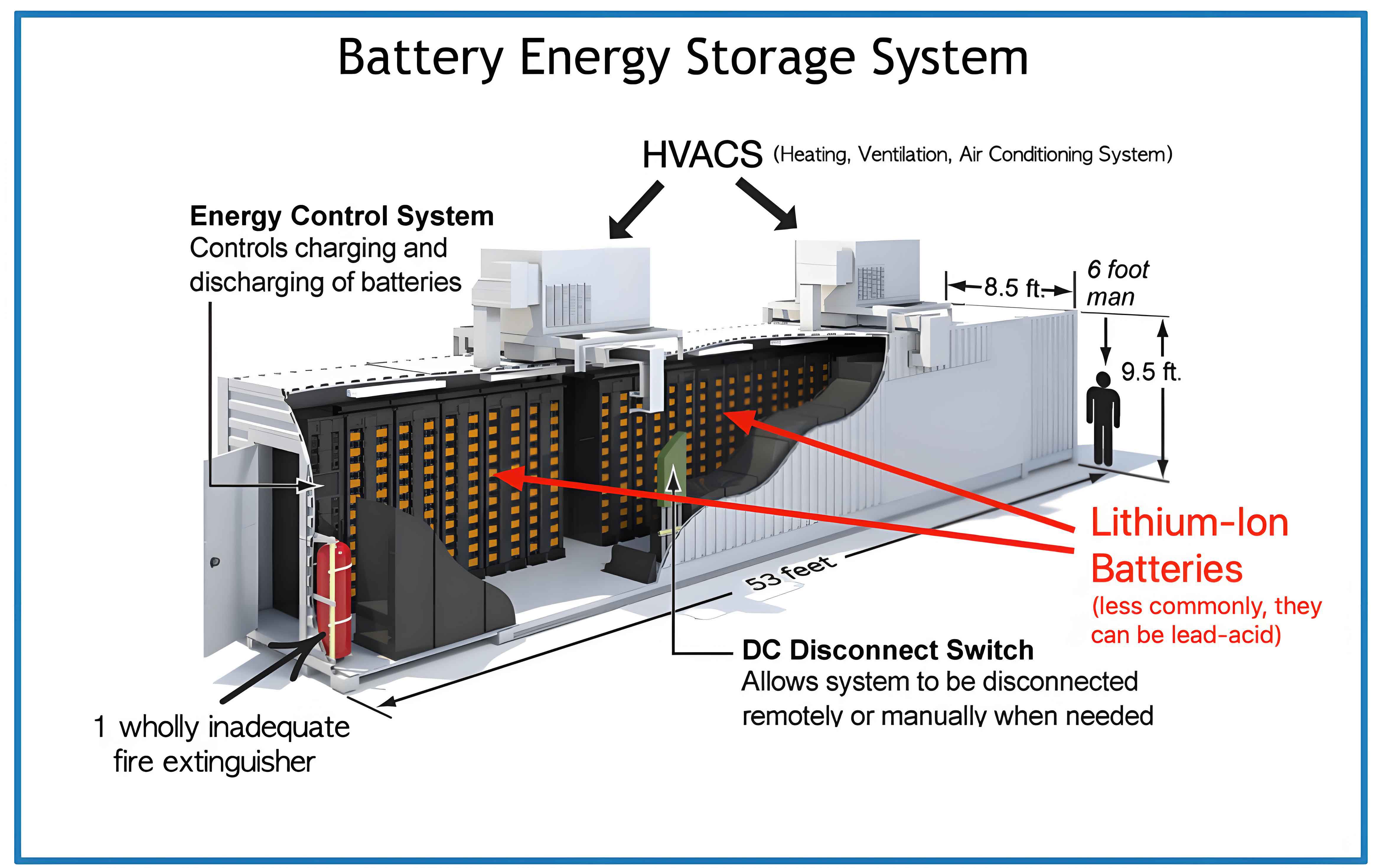
From an implementation perspective, the control algorithms can be deployed in energy management systems with moderate computational requirements. The fuzzy logic and mode switching logic are rule-based, allowing for real-time execution. The battery energy storage system itself, as depicted in the included image, consists of battery packs, power conversion systems, and control hardware, all of which must be scaled appropriately for grid applications. The image illustrates a typical battery energy storage system setup, highlighting its compact and modular design suitable for integration with existing infrastructure. Overall, this strategy contributes to the evolving landscape of smart grids, where battery energy storage system play a pivotal role in maintaining stability amid energy transitions.
Conclusion
We have developed an adaptive frequency regulation strategy for battery energy storage system-assisted secondary frequency control, focusing on signal decomposition and mode switching. The strategy dynamically allocates regulation signals between thermal units and the battery energy storage system based on sensitivity, state of charge, and frequency deviation states. It incorporates state of charge constraints to prevent overuse and employs an adaptive return gain to optimize power sharing. Simulation results demonstrate that our approach improves frequency performance metrics—such as maximum deviation, RMS error, and settling time—while maintaining the battery energy storage system’s state of charge within safe limits. Compared to conventional methods, it offers better flexibility and resource complementarity, making it a promising solution for grids with high renewable energy integration. The battery energy storage system thus proves to be a valuable asset for frequency regulation, and our control strategy enhances its effectiveness and longevity. Future research should explore economic optimizations and integration with other storage technologies to further advance grid resilience.