
Photovoltaic and wind power generation have characteristics of volatility, intermittency, and randomness. It is difficult for independent operating systems of new energy generation to provide continuous and stable energy output, resulting in significant errors between actual power generation and prediction. After a high proportion of integration into the power system, the issue of balancing the output characteristics of new energy with the load of the power system becomes prominent. It is necessary to configure large-scale energy storage stations to improve the power output characteristics of the entire power generation system, effectively reduce wind and solar losses, and promote the consumption of renewable energy. Under the “dual high” characteristics of the new power system, energy storage technology can effectively improve the regulation and support capabilities of the system, providing important guarantees for the safe and stable operation of the power grid. The configuration of battery energy storage systems on the source network side has become one of the main technical means to solve the problem of wind and solar energy consumption.
With technological breakthroughs and industrial upgrades, LFP batteries have achieved significant improvements in key indicators such as efficiency, energy density, and cycle life. Compared to other new energy storage systems, the installation of LFP battery energy storage system equipment is flexible, and the project construction cycle is shorter. In recent years, the installed capacity of LFP battery energy storage systems has experienced explosive growth, achieving a transformation from industrial application to scale, and occupying a dominant market position in the distribution and storage of new energy stations. In the actual operation of renewable energy stations, the thermal stability and safety issues of the configured battery system are crucial, as they are closely related to the service life of the system and directly affect the economy and safety of the entire new energy station.
To optimize the thermal stability and safety of the LFP battery energy storage system, from the perspective of system integration, taking the liquid cooled energy storage system as an example, the safety of the LFP battery system is developed and designed from three aspects: thermal management, fire protection, and electrical. Through thermal simulation and related experimental calibration, the thermal management optimization design of liquid cooled battery packs was carried out, and the thermal load of energy storage battery packs at different magnification rates was analyzed and compared. The system characteristics of LFP battery energy storage in the “new energy+energy storage” application scenario were briefly explained. In addition, based on the analysis of the mechanism of battery thermal runaway, a battery pack level fire protection optimization plan was proposed, and a systematic discussion was conducted on the safety protection strategy and the multiple redundancy design of fuses.
1.System characteristics of LFP battery energy storage
As the proportion of new energy generation increases, the system lacks sufficient flexibility to adjust power sources, making it difficult to coordinate and optimize the scheduling and operation of new energy generation plans. In the combination scenario of “new energy+energy storage”, the battery energy storage system provides backup capacity and power support, improves the power output characteristics of the entire power generation system by timely absorbing or releasing electricity, and effectively alleviates the contradiction between new energy generation and the power system that requires real-time balance. Taking into account factors such as economy, safety, and industrial maturity, LFP battery energy storage has become the main solution for new energy distribution and storage at present, achieving development from industrial application to scale. The LFP battery energy storage system consists of a battery prefabrication compartment, a boost converter integrated machine, and an energy management system.
In renewable energy generation systems, the topology architecture of energy storage systems has a significant impact on the construction of energy storage power plants, which can be divided into centralized, distributed, and high-voltage cascaded topologies from a technical perspective. At present, the source network side storage is mainly centralized (large storage), while the user side industrial and commercial storage is mainly distributed.
2.Research on thermal management of energy storage systems
The battery pack, as the smallest modular unit of the energy storage system, directly determines the thermal performance of the energy storage system. To effectively validate the thermal management scheme of liquid cooling platform products, it is necessary to combine thermal simulation methods and relevant experimental testing techniques to conduct a comprehensive evaluation and research on the thermal characteristics of battery packs. The single pack specification is 1P52S, consisting of 52 280 Ah lithium iron phosphate cells with a rated power of P=280 × three point two × 52=46 592 W. In energy storage plants configured on the new energy side, the operating conditions are mostly 0.5 times the rated power (0.5 P), and the average thermal power for charging and discharging a single LFP cell is calculated as 12.5 W. The weight of each cell is m=5.4 kg, and the specific heat capacity of the battery is taken as 1.0 kJ/(kg · ℃). According to the calculation of 0.5 P working condition, the theoretical heating power of the battery pack is:
2.1 Pack Thermal Performance Optimization
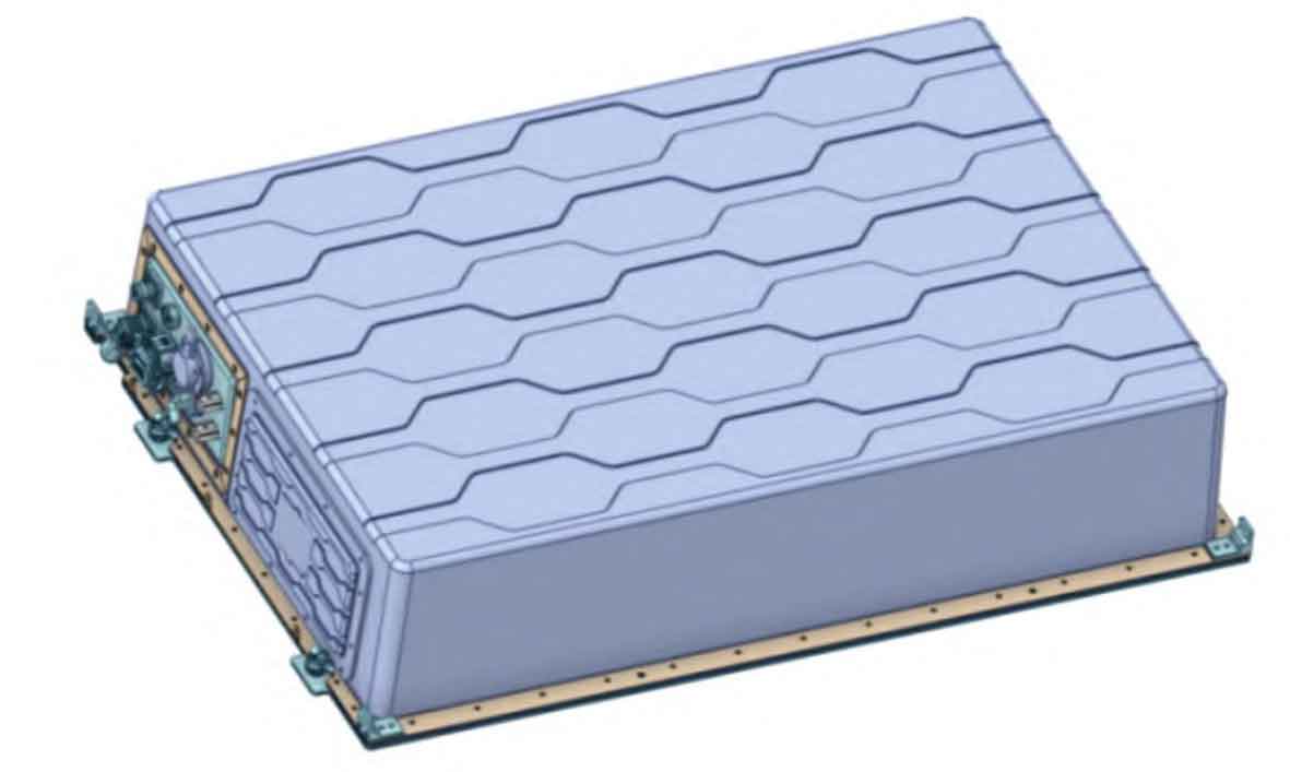
To optimize the heat dissipation performance of the battery pack, the liquid cooled plate adopts microchannel technology, using a mass fraction of 50% ethylene glycol solution as the cooling medium, and effectively filling the gap between the battery cell and the liquid cooled plate through thermal conductive adhesive filling, reducing thermal resistance and improving heat transfer efficiency. Using parameters such as 5 L/min flow rate, 20 ℃ inlet temperature, 25 ℃ ambient temperature, and heating power as boundary conditions, and considering the specific heat capacity of the battery, thermodynamic simulation was conducted on the liquid cooled battery pack. A temperature sampling point was set on each aluminum bar according to the BMU temperature sampling point position. The mechanical structures of the simulation model have good contact, and the effects of material property changes, natural air convection, aluminum exhaust Joule heat, and radiation heat transfer are ignored during the calculation process. The three-dimensional structure of the battery pack is shown in Figure 1.
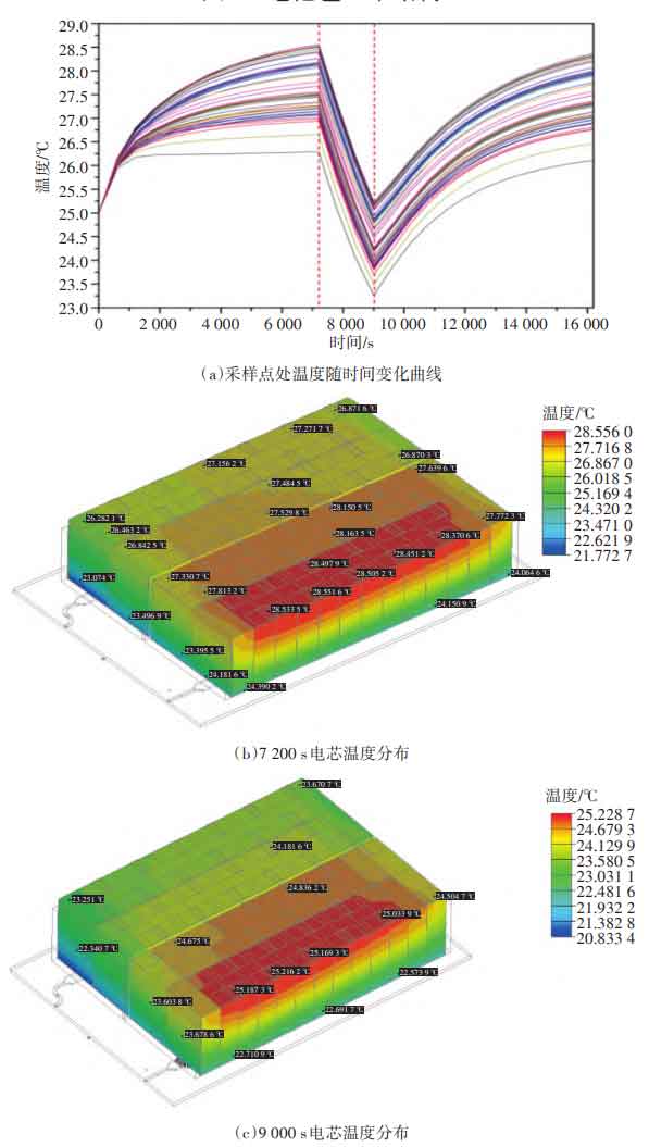
From Figure 2, it can be seen that the temperature change curve and temperature distribution at the sampling point of the aluminum battery pack indicate that the operating conditions are 0.5 P discharge for 2 hours, standing for 0.5 hours, 0.5 P charging for 2 hours, and one cycle t=16 200 seconds, where the discharge cycle ends at 7 200 seconds and the standing for 9 000 seconds. At 7200 seconds, the highest sampling temperature of the aluminum strip is 28.6 ℃, the lowest sampling temperature is 26.3 ℃, the maximum temperature difference is 2.3 ℃, the temperature difference between the inlet and outlet is 2.3 ℃, and the maximum temperature difference on the surface of the single cell is 4.7 ℃. At 9000 seconds, the highest sampling temperature of the aluminum strip is 25.3 ℃, the lowest sampling temperature is 23.3 ℃, the maximum temperature difference is 2.0 ℃, the temperature difference between the inlet and outlet is 1.2 ℃, and the maximum temperature difference on the surface of the single cell is 3.5 ℃. Under the rated working condition of 0.5 P, the maximum temperature of the battery cell during the cycle can be controlled within 29 ℃, within the optimal temperature range of the battery cell (15 ℃~35 ℃); The temperature rise and temperature difference of the battery cell during the cycle are controlled within 6.0 ℃ and 2.5 ℃, both of which are at an optimal level.
To fully validate the thermal design simulation results, a single pack was calibrated for charging and discharging electric heating performance experiments, as shown in Figure 3. After standing at ambient temperature for 5 hours, conduct a charging and discharging cycle test at 0.5 times the rated power (0.5 P), and continuously start the chiller throughout the entire process.
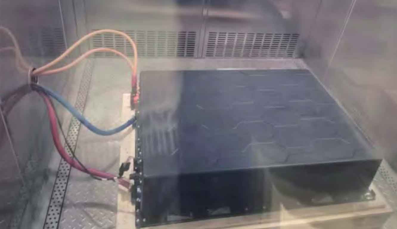
The experiment showed that by optimizing the thermal management design of the liquid cooled battery pack, under a working condition of 0.5 P, the temperature at the electrode ear of the battery cell collected by BMS after the charging and discharging stage was between 29 ℃ and 32 ℃, and the battery cell was in the optimal temperature range throughout the entire test cycle. The maximum temperature difference inside the battery pack measured is ≤ 2 ℃, which meets the development needs of liquid cooled battery pack products. At the same time, it provides an effective reference for the research on refined thermal management of battery packs.
2.2 Pack thermal characteristics at different magnification
Under different charging and discharging rates, there are significant differences in the heat production of the cell. Generally speaking, the higher the charging and discharging rate, the greater the thermal power of the cell. Taking 280 Ah lithium iron phosphate battery cells as an example, under 0.5 P working condition, the average thermal power during charging and discharging is 12.5 W, while under 1 C working condition, the average thermal power during charging and discharging is 32 W~40 W. At high magnification, the overall thermal load of the battery pack will be significantly increased. To quantitatively analyze the relationship between charge discharge rate and thermal load of battery packs, thermal management research experiments were conducted on liquid cooled battery packs under operating conditions of 0.25 P, 0.5 P, 0.75 P, and 1 P, as shown in Figure 4.
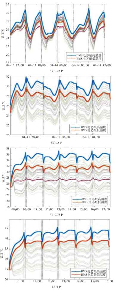
The results show that under 0.25 P operating conditions, the temperature at the electrode ear of the battery cell collected by BMS after equilibrium is between 24 ℃ and 31 ℃; Under the working condition of 0.5 P, the temperature at the electrode ear of the battery cell collected by BMS after balance is between 27 ℃ and 32 ℃; Under the working condition of 0.75 P, the temperature at the electrode ear of the battery cell collected by BMS after balance is between 29 ℃ and 37 ℃; Under 1P working condition, the temperature at the electrode ear of the battery cell collected by BMS after balance is between 35 ℃ and 45 ℃; Under high rate charging and discharging (1P) conditions, the temperature of the battery pack can be effectively controlled within 45 ℃ after the charging and discharging stage, and the maximum temperature difference inside the pack is ≤ 5 ℃
3.Pack level fire protection strategy and plan
The fire protection design of energy storage systems is crucial in minimizing accident risks, protecting personnel and property safety, and improving the reliability and stability of the entire energy system.
3.1 Mechanism analysis of battery thermal runaway
From the analysis of the triggering mechanism of battery safety accidents, the behavior of out of control/internal short circuit caused by contact heating can be roughly divided into mechanical abuse, electrical abuse, and thermal abuse. Among them, mechanical abuse causes mechanical deformation of the battery and physical rupture of the separator, triggering internal short circuits in the battery; Electric abuse leads to overcharging, overdischarge, etc., which leads to lithium precipitation and dendrite growth in the battery, causing short circuits within the battery; Thermal abuse causes the diaphragm to contract and collapse on a large scale, causing a short circuit in the battery. When a lithium-ion battery experiences an internal short circuit, it generates a large current and a large amount of local heat, ultimately leading to thermal runaway. After the battery burns and produces an open flame, it is difficult to effectively suppress it through conventional means.
3.2 Fire protection strategy and plan optimization
From the mechanism analysis, it can be seen that the battery should adopt a safety strategy of prevention first and combining prevention and fire prevention. For liquid cooled energy storage prefabricated tanks, the fire protection system should adopt a fully automatic pack level fire protection design scheme. The key to the Pack level fire protection plan is to equip it with external detectors and fire extinguishing devices, which can perform composite detection (smoke, temperature, CO, VOC, etc.) on each battery pack, thereby achieving early thermal runaway perception, intelligent judgment, and early suppression of the battery pack. The prefabricated cabin fire protection system includes external detection, cabin level detection, fire controller, emergency start stop button, sound and light alarm, gas fire extinguishing device, gas spraying indicator light, and other components. With Pack as the minimum protection unit, it is equipped with a gas-liquid two-phase fire extinguishing technology solution of perfluorohexane fire extinguishing agent. In conjunction with the “three in one” external detector, each battery pack is comprehensively monitored and detected in real-time.
4.Electrical safety optimization of energy storage system
The electrical safety of the energy storage system needs to consider external short circuits in the battery system and internal short circuits in the battery system. In the event of an external short circuit in the battery system, on-site fault isolation is achieved through BMS, which removes the problematic battery cluster from operation and reports protection information. In the event of an internal short circuit in the battery system, there is a risk of BMS leakage. By configuring hardware protection devices such as relays, circuit breakers, and fuses, fault isolation is achieved to ensure system safety.
4.1 Short circuit protection design within the battery system
The internal short circuit protection device of the battery system needs to consider the segmented capacity and fuse time, and achieve graded protection function and battery cell safety through multiple redundant designs, thereby reducing economic losses caused by faults. Referring to the short circuit curve of the 280 Ah battery cell, the peak short circuit current is 3000 A. Considering that the internal resistance of the short circuit conductor has a significant impact on the short circuit current during the experiment, and that the short circuit within the battery cluster is usually not a single cell short circuit, it is necessary to consider the short circuit current of Pack level and above. Through the experiment, the short circuit current obtained is 12000 A.
Considering factors such as temperature correction, the rated current of the fuse is usually 1.5 to 2 times the rated current of the line, and the rated current of the fuse is selected to be 250 A; The fuse for the battery should be selected based on the short-circuit current of the battery and the fuse melting curve. The maximum segmented capacity of the selected fuse is 250 kA, which meets the breaking requirements under short-circuit conditions.
According to the time current curve of the selected fuse and pack fuse in the high-voltage box, the short-circuit current is taken as the test value of 12000 A. The pre arc time of the high-voltage box fuse is:
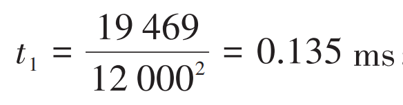
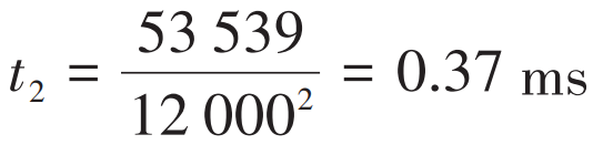
Fusing time:
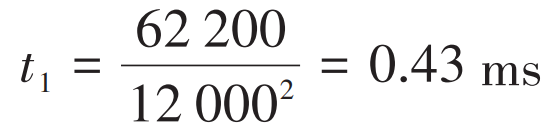
Pre arc time of fuse within the pack:
Fusing time:
The pre arc time of the high-voltage box fuse is 0.135 ms and the fusing time is 0.37 ms, while the pre arc time of the pack fuse is 0.43 ms and the fusing time is 1.64 ms. Therefore, under short circuit conditions, the fuse inside the high-voltage box is protected by fusing before the pack, and its fusing time is lower than the pre arc time of the pack fuse, achieving graded protection.
4.2 Short circuit protection strategy outside the battery system
If the voltage, current, temperature and other analog quantities of the battery exceed the safety protection threshold, the battery management system can achieve on-site fault isolation, remove the problematic battery cluster from operation, and report protection information at the same time.
The fire linkage control unit analyzes and processes data from detectors, and the specific control logic is as follows:
(1) First level alarm. There is no external signal output, the detector increases the sampling frequency, and the controller records alarm information.
(2) Secondary alarm. It is determined that there is a safety hazard in the energy storage plant. The fire alarm controller issues an alarm and transmits the data to the BMS system (which is then transmitted to the EMS system). The fire linkage control unit controls the alarm system’s audible and visual alarms to rapidly beep and flash, and starts the exhaust system. At the same time, the local controller disconnects the main power distribution switch in the battery compartment; EMS controls PCS shutdown and disconnects the DC side contactor to achieve electrical isolation of the battery compartment.
(3) Level 3 alarm. Determine if a thermal runaway fire (with open flames) has occurred in the space of the energy storage station. The energy storage station will use a fire alarm controller to interlock and shut down the exhaust system, and activate the package level fire extinguishing device to fully submerge the entire battery compartment.
5. Conclusion
Driven by the energy transformation, renewable energy is thriving and facing challenges. The application form of “renewable energy+energy storage system” is one of the main forms of renewable energy utilization now and in the future. Through thermal simulation and related experimental calibration methods, the thermal management optimization design of the liquid cooled battery pack was carried out. The results showed that under 0.5 P working condition, the optimized design scheme can achieve a temperature difference within the package of ≤ 2 ℃ and a maximum temperature of ≤ 32 ℃, and control the temperature within 45 ℃ at high magnification (1 P). In addition, based on the analysis of the mechanism of battery thermal runaway, a battery pack level fire protection scheme has been launched, and a systematic analysis has been conducted on the protection strategy and multiple redundancy design of fuses, providing important reference and support for improving the reliability of energy storage systems in new energy generation systems.