
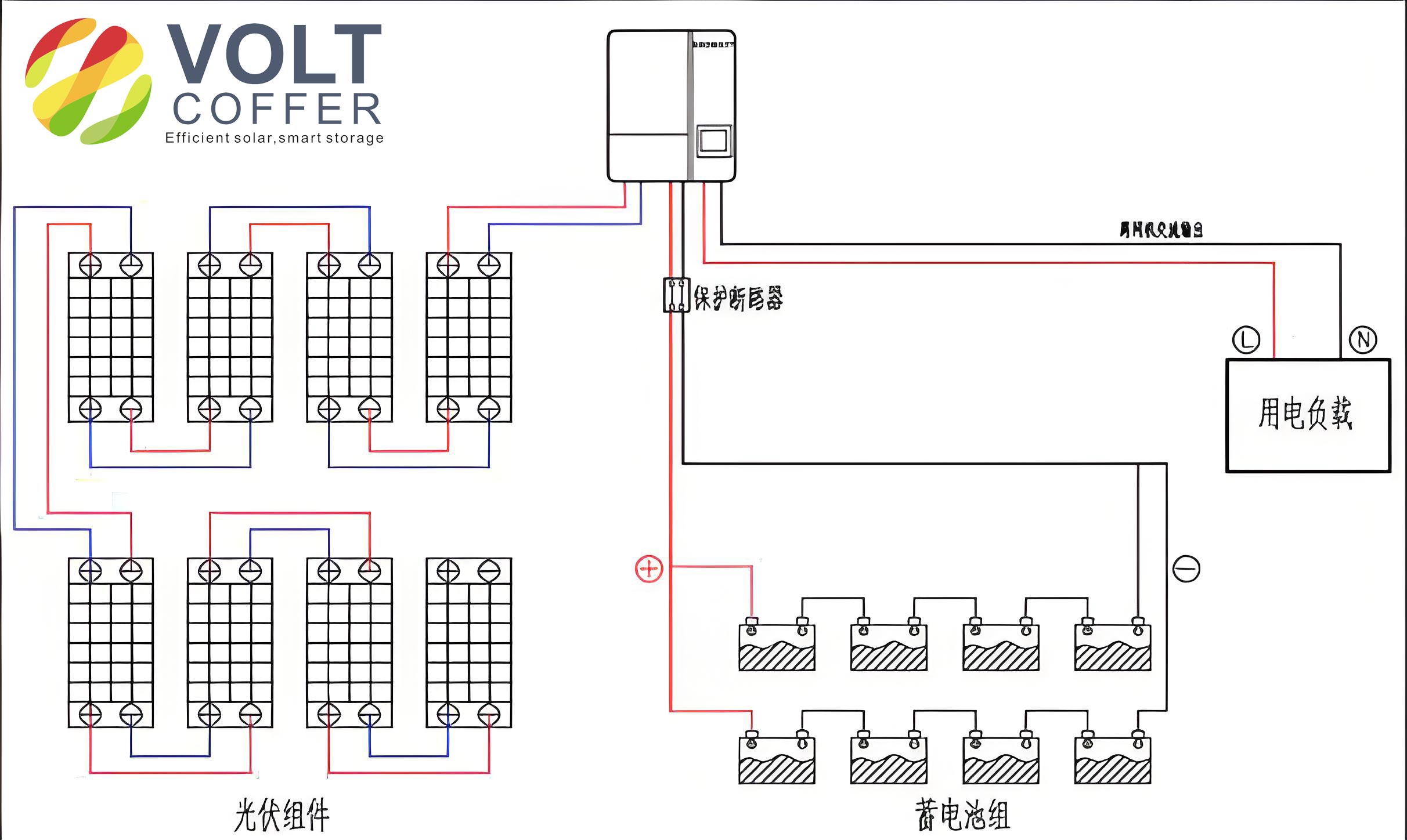
Energy serves as the driving force for human progress and social development. With the rapid growth of the global economy and industrialization, the consumption of non-renewable energy sources like fossil fuels has increased dramatically. The extensive use of non-renewable energy has led to a series of issues, such as global warming, the greenhouse effect, rising sea levels, air pollution, and the gradual depletion of fossil fuels. These challenges have compelled humanity to vigorously develop and utilize renewable, green, and pollution-free new energy sources. Among these, solar energy is one of the most widely exploited resources, with corresponding solar equipment becoming increasingly mature. The off-grid solar photovoltaic energy storage power generation system is a typical application that converts solar radiation into electricity through photovoltaic panels, uses a solar charge controller to supply power to loads and charge batteries, and relies on batteries to power loads during periods without sunlight or at night. Off-grid solar photovoltaic energy storage systems are typically deployed in vast grasslands, remote mountainous areas, isolated islands, or other electrified regions, primarily operating in outdoor environments.
The off-grid solar system integrated machine is a key component of the off-grid solar photovoltaic energy storage system, and the rationality of its structural design directly impacts the safety and service life of the entire system. This study focuses on the structural optimization of an off-grid solar system integrated machine to enhance its stiffness, strength, and vibration characteristics. We begin by employing ANSYS Workbench for static and modal analysis to identify weak points in the machine’s structure. Based on the analysis results, we proceed with optimization design to improve these aspects. Finally, we validate the optimized design through comparative static and modal analysis, demonstrating significant improvements in performance. This approach provides a methodological foundation for the design and enhancement of off-grid solar system integrated machines.
The off-grid solar system integrated machine primarily consists of a frame structure, energy storage battery modules, a transformer module, and a main controller module. The original design featured a three-layer compartment structure with overall dimensions of 590 mm × 300 mm × 600 mm. The bottom layer supported the energy storage battery module, the middle layer housed the transformer module, and the top layer contained the inverter-integrated main controller module. Each layer included square sheet metal components as support plates, and the exterior was enclosed with sheet metal panels fastened to the frame via bolts and welding. However, this configuration exhibited vulnerabilities in stiffness and strength, leading to excessive deformation and vibration issues during outdoor operation. The vibration source mainly originated from the transformer module, which operates at frequencies between 50 Hz and 60 Hz, posing a risk of resonance.
To address these challenges, we first established the theoretical foundation for finite element analysis. The general equation of dynamic equilibrium, derived from Newton’s second law, is expressed as:
$$ M\ddot{x} + C\dot{x} + Kx = F(t) $$
where \( M \) is the mass matrix, \( C \) is the damping matrix, \( K \) is the stiffness matrix, \( x \) is the displacement vector, \( F(t) \) is the force vector, \( \dot{x} \) is the velocity vector, and \( \ddot{x} \) is the acceleration vector. For linear static analysis, time-dependent terms are neglected, simplifying the equation to:
$$ Kx = F $$
Modal analysis, which computes the vibration characteristics of a structure, is fundamental to dynamic analysis. It determines natural frequencies and mode shapes, enabling structural optimization to avoid resonance. Ignoring external excitation and damping, the equation reduces to:
$$ M\ddot{x} + Kx = 0 $$
For free harmonic vibration, the equation simplifies to:
$$ (K – \omega_i^2 M)\phi_i = 0 $$
where \( \omega_i \) is the natural frequency and \( \phi_i \) is the mode shape for the i-th mode.
We developed a finite element model of the off-grid solar system integrated machine by simplifying the complex geometry to facilitate analysis. The simplified model was imported into ANSYS Workbench, where material properties were defined and meshing was performed. The frame materials included galvanized steel and aluminum alloy, chosen for their high tensile strength, reliability, oxidation resistance, and corrosion resistance. The material properties are summarized in Table 1.
| Material | Density (kg/m³) | Elastic Modulus (Pa) | Poisson’s Ratio |
|---|---|---|---|
| Aluminum Alloy | 2.77 × 10³ | 7.1 × 10¹⁰ | 0.33 |
| Galvanized Steel | 7.85 × 10³ | 2.0 × 10¹¹ | 0.29 |
Mesh generation was conducted with a cell size of 10 mm and medium smoothness, resulting in 134,110 elements and 279,939 nodes. Boundary conditions were applied based on actual operational loads: the machine’s self-weight and component pressures. The bottom four fixed bases were constrained, and concentrated forces of 294 N, 4.9 N, and 9.8 N were applied to the support plates of the bottom, middle, and top layers, respectively, representing the weights of the battery module (30 kg), inverter module (0.5 kg), and main controller module (1 kg).
Static analysis revealed that the maximum stress of 35.125 MPa occurred at the bottom support plate and side panels, while the maximum deformation of 1.4338 mm was observed in the central region of the bottom support plate. These results indicated inadequate stiffness and strength, necessitating optimization. Modal analysis extracted the first six natural frequencies and mode shapes, as shown in Table 2 and Figure 1. The frequencies ranged from 31.008 Hz to 58.038 Hz, closely overlapping with the transformer’s vibration frequency of 50–60 Hz, indicating a high risk of resonance.
| Mode | Frequency (Hz) | Mode Shape Description |
|---|---|---|
| 1 | 31.008 | Lateral vibration of side panels with slight vertical vibration of top and bottom plates |
| 2 | 31.889 | Lateral vibration of side panels |
| 3 | 48.696 | Vertical vibration of middle and top support plates |
| 4 | 48.909 | Vertical vibration of middle and top support plates with slight side panel vibration |
| 5 | 51.270 | Lateral vibration of side panels with vertical vibration of top, bottom, and middle plates |
| 6 | 58.038 | Lateral vibration of side panels with vertical vibration of top and bottom plates |
The optimization design focused on two key aspects: (1) converting the three-layer structure into a two-layer compartment to reduce the overall height to 460 mm, with the upper layer housing the transformer and main controller modules and the lower layer containing the battery module, resulting in compact dimensions of 540 mm × 300 mm × 460 mm; and (2) adding an internal aluminum alloy support frame to enhance rigidity, including additional beams for the bottom layer to support the heavy battery module and reinforcements for the upper layer and top plate. The aluminum frame was connected to the sheet metal panels via bolts, screws, and angle brackets.
After optimization, static and modal analyses were repeated. The results showed a maximum stress of 12.013 MPa and a maximum deformation of 0.2096 mm, representing reductions of 65.8% and 85.4%, respectively. The first six natural frequencies increased to a range of 143.04–184.78 Hz, effectively avoiding the transformer’s excitation frequency. A comparative summary of pre- and post-optimization parameters is provided in Table 3.
| Parameter | Pre-Optimization | Post-Optimization | Improvement |
|---|---|---|---|
| Max Deformation (mm) | 1.4338 | 0.2096 | 85.4% reduction |
| Max Stress (MPa) | 35.125 | 12.013 | 65.8% reduction |
| 1st Natural Frequency (Hz) | 31.008 | 143.04 | 361.3% increase |
| 2nd Natural Frequency (Hz) | 31.889 | 146.69 | 360.0% increase |
| 3rd Natural Frequency (Hz) | 48.696 | 178.53 | 266.7% increase |
| 4th Natural Frequency (Hz) | 48.909 | 182.30 | 272.7% increase |
| 5th Natural Frequency (Hz) | 51.270 | 184.37 | 259.5% increase |
| 6th Natural Frequency (Hz) | 58.038 | 184.78 | 218.4% increase |
The enhanced off-grid solar system integrated machine demonstrates superior performance, with significantly improved stiffness, strength, and vibration characteristics. The optimization effectively mitigates resonance risks and ensures reliable operation in outdoor environments. This study underscores the importance of finite element analysis in the design process of off-grid solar systems and provides a robust framework for future improvements. The methodologies applied here can be extended to other renewable energy equipment, contributing to the advancement of sustainable energy solutions.
In conclusion, the integration of static and modal analysis into the design cycle of an off-grid solar system integrated machine enables the identification and rectification of structural weaknesses. The optimized design not only meets operational requirements but also extends the machine’s lifespan and reliability. As the demand for off-grid solar systems continues to grow, such analytical approaches will play a crucial role in ensuring the efficiency and durability of these systems, ultimately supporting the global transition to renewable energy.