
In recent years, the adoption of off-grid solar systems has surged, particularly in remote and inaccessible regions such as islands, deserts, and rural areas where connection to the main power grid is impractical. These systems provide a reliable source of electricity by harnessing solar energy, storing it in batteries, and supplying power to loads independently. However, the complexity of off-grid solar systems—comprising solar panels, charge controllers, batteries, and inverters—makes them prone to various faults over time. Common issues include wiring disconnections, solar panel degradation, battery performance decline, and controller malfunctions, which often escalate with system age. The challenge is compounded by the geographical isolation of these installations, leading to high maintenance costs and prolonged downtime when faults occur. Existing monitoring solutions, such as those developed for grid-tied photovoltaic plants, are inadequate for off-grid applications due to differences in system architecture and fault characteristics. For instance, while cloud-based platforms like Huawei’s FusionSolar or SMA’s ZeverCloud offer advanced monitoring for large-scale grid-connected systems, they do not address the unique needs of small-scale off-grid solar systems. This gap in technology motivated me to develop a low-power, intelligent fault diagnosis instrument specifically designed for 24V off-grid solar systems. The instrument enables real-time detection of faults without disrupting system operation, leveraging wireless communication for remote alerts. In this article, I detail the hardware and software design of this diagnostic tool, present experimental validation, and discuss its implications for improving the reliability and maintenance of off-grid solar systems.
The core objective of this project was to create a portable, user-friendly device that could identify common faults in 24V off-grid solar systems through non-intrusive measurements. Off-grid solar systems often operate in harsh environments with limited technical support, making early fault detection crucial to prevent total system failure. By integrating voltage, current, and temperature sensors with a microcontroller and wireless module, the diagnosis instrument can analyze system parameters in real-time and pinpoint issues such as open circuits, short circuits, overcharging, over-discharging, and battery overheating. The design prioritizes low power consumption to ensure compatibility with off-grid setups, where energy efficiency is paramount. Moreover, the instrument uses clamp-on probes for easy attachment to existing wiring, eliminating the need for system modification during diagnostics. This approach not only enhances accessibility for non-experts but also reduces the time and cost associated with traditional troubleshooting methods. The following sections elaborate on the hardware architecture, software algorithms, and experimental tests that validate the instrument’s performance, emphasizing its potential to revolutionize maintenance practices for off-grid solar systems worldwide.
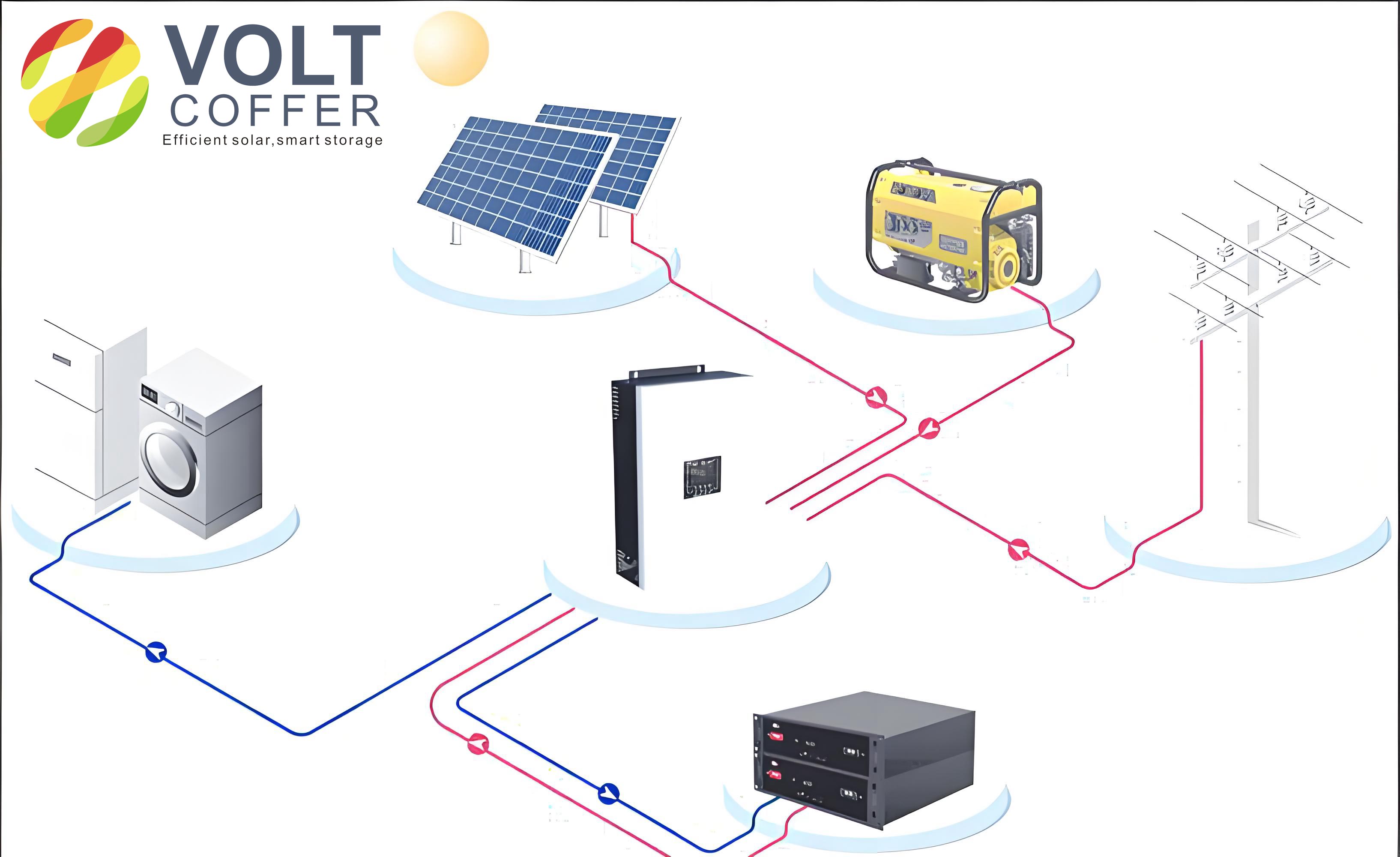
To achieve comprehensive fault diagnosis in off-grid solar systems, the hardware design of the instrument incorporates multiple sensing modules, a central processing unit (CPU), and communication interfaces. The overall schematic, as illustrated in the principles, involves connecting current clamps to the wiring between solar panels and the charge controller (point a in the system diagram), voltage clamps at the interfaces of the controller with solar panels (point a), batteries (point b), and loads (point c), and temperature probes attached to the battery surface and ambient environment. This configuration allows for simultaneous monitoring of key parameters without interfering with the normal operation of the off-grid solar system. The CPU, based on the PIC18F6720 microcontroller, serves as the brain of the instrument, processing analog and digital signals from various sensors. Its built-in analog-to-digital converter (ADC) modules transform sensor outputs into digital values for analysis, while its low-power features ensure minimal energy draw from the system under test. The power supply circuit, derived from the 24V off-grid solar system itself, includes voltage regulation to provide stable 5V and 3.3V rails for the components, enhancing reliability in fluctuating energy environments typical of off-grid setups.
Voltage detection is handled by Hall-effect voltage transducers, specifically the HNV025A modules, which sample voltage signals at points a, b, and c. These transducers scale down the high voltages (e.g., up to 32V from solar panels) to lower levels compatible with the CPU’s ADC inputs. The voltage signal conditioning circuit involves operational amplifiers configured as voltage followers to buffer the signals and reduce noise. For instance, the voltage at point b (battery interface) is critical for identifying overcharge or over-discharge conditions, and it is processed using the formula: $$ V_{b\_scaled} = k_v \times V_b $$ where \( V_b \) is the actual battery voltage, and \( k_v \) is the scaling factor of the transducer (e.g., 0.01 for a 100:1 ratio). Similarly, current detection employs clamp-on current probes like the CHCS-LS08, which convert current flows into proportional voltage signals. The relationship is given by: $$ V_{out} = k_i \times I_a $$ where \( I_a \) is the current in the solar panel-controller line, and \( k_i \) is the sensitivity of the current probe (e.g., 10 mV/A). This voltage output is then fed into the ADC for digitization. Temperature monitoring uses DS18B20 digital sensors, which provide direct digital readings via a one-wire communication protocol, eliminating the need for additional ADC channels. The sensors measure battery temperature (\( T_{bat} \)) and ambient temperature (\( T_{env} \)), with the difference \( \Delta T = T_{bat} – T_{env} \) used to detect overheating faults.
The remote communication module, an ATK-SIM800C GPRS chip, enables wireless transmission of fault data to a central server. This module connects to the CPU via a UART interface, allowing it to send SMS alerts or data packets over cellular networks. The liquid crystal display (LCD) and keyboard interfaces provide local interaction, enabling users to view real-time parameters, set thresholds, and initiate diagnostics. A summary of the key hardware components and their specifications is presented in Table 1, highlighting the integration of these elements into a cohesive system for fault diagnosis in off-grid solar systems.
| Component | Model/Specification | Function | Key Parameters |
|---|---|---|---|
| Microcontroller | PIC18F6720 | Central processing | 10-bit ADC, low-power mode |
| Voltage Transducer | HNV025A | Voltage sampling | Scaling factor: 0.01, input range: 0-50V |
| Current Probe | CHCS-LS08 | Current measurement | Sensitivity: 10 mV/A, clamp-on design |
| Temperature Sensor | DS18B20 | Temperature monitoring | Resolution: 0.0625°C, one-wire interface |
| GPRS Module | ATK-SIM800C | Wireless communication | GSM/GPRS bands, UART interface |
| Power Supply | Regulated circuit | Voltage regulation | Input: 24V DC, outputs: 5V/3.3V |
In designing the circuitry, I prioritized robustness and accuracy to handle the variable conditions of off-grid solar systems. The voltage and current sensing paths include filtering capacitors and resistors to mitigate electromagnetic interference, which is common in environments with inverters and charge controllers. For example, the voltage follower circuit uses an op-amp with high input impedance to prevent loading effects, ensuring that the measured voltages reflect the true system state. The current probe output is conditioned through a gain stage to match the ADC’s input range, with the transfer function: $$ V_{ADC} = G \times V_{out} $$ where \( G \) is the gain set by feedback resistors. Additionally, the GPRS module is configured with an external antenna to maintain connectivity in remote areas, a critical feature for off-grid solar systems deployed in isolated locations. The entire instrument is housed in a compact, durable enclosure with probe connectors labeled for easy use, making it accessible even for personnel with limited technical expertise. This hardware foundation enables the instrument to capture high-fidelity data, which is then processed by the software to diagnose faults accurately.
The software design of the fault diagnosis instrument revolves around a structured algorithm that processes sensor data, identifies faults based on predefined thresholds, and manages user interactions and communications. Upon power-up, the instrument initializes its peripherals, including the ADC, UART for GPRS, and I/O pins for the LCD and keyboard. Users are prompted to set configuration parameters such as the diagnostic interval (e.g., every 5 minutes) and temperature thresholds (e.g., maximum \( \Delta T \) of 30°C). These settings are stored in non-volatile memory to persist across reboots, ensuring consistency in long-term monitoring of off-grid solar systems. The main program loop begins with data acquisition from all sensors: voltages \( U_a \), \( U_b \), and \( U_c \); current \( I_a \); and temperatures \( T_{bat} \) and \( T_{env} \). Each reading is averaged over multiple samples to reduce noise, using a moving average filter implemented in software. For instance, the voltage at point b is computed as: $$ U_b = \frac{1}{N} \sum_{i=1}^{N} U_{b_i} $$ where \( N \) is the number of samples (e.g., 10), and \( U_{b_i} \) is the i-th ADC reading scaled back to the actual voltage using the transducer factor.
Fault diagnosis is performed by comparing the processed data against a fault table that maps parameter combinations to specific issues. This table, derived from empirical studies of off-grid solar systems, includes logical conditions that trigger fault flags. For example, if \( U_a = 0 \) V and \( I_a = 0 \) A, it indicates an open circuit between the solar panels and controller. Similarly, if \( U_b < 21.6 \) V, the battery is likely over-discharged, while \( U_b > 28.8 \) V suggests overcharging. The temperature difference \( \Delta T = T_{bat} – T_{env} \) is checked against a threshold (e.g., 30°C) to detect battery overheating. The diagnosis logic can be expressed as a series of conditional statements, such as:
$$ \text{if } (U_a == 0) \land (I_a == 0) \rightarrow \text{Fault: Open circuit at solar-controller interface} $$
$$ \text{if } (21.6 < U_b < 28.8) \land (U_a > 32) \land (I_a == 0) \rightarrow \text{Fault: Controller charging failure} $$
$$ \text{if } (U_b == 0) \rightarrow \text{Fault: Open circuit at battery-controller interface} $$
These rules are implemented in the software as a state machine that evaluates each condition sequentially. If no faults are detected, the instrument waits for the user-defined interval before repeating the cycle. If a fault is identified, it is displayed on the LCD, and the user is prompted to send an alert via GPRS. The communication protocol involves formatting the fault data into a JSON-like string and transmitting it to a cloud server for remote monitoring.
To enhance reliability, the software includes error-handling routines for sensor failures or communication dropouts. For instance, if the DS18B20 sensor does not respond, the software retries the reading up to three times before flagging a sensor error. The GPRS transmission is handled asynchronously to avoid blocking the main loop, using interrupt-driven routines to manage data sending and acknowledgment. A summary of the fault diagnosis logic is provided in Table 2, which outlines the key parameters and their corresponding fault indications for off-grid solar systems. This table serves as a quick reference for users interpreting the instrument’s outputs.
| Parameter Condition | Fault Type | Description |
|---|---|---|
| \( U_a = 0 \) V | Open circuit | Wiring disconnect between solar panels and controller |
| \( 21.6 < U_b < 28.8 \) V, \( U_a > 32 \) V, \( I_a = 0 \) A | Controller charging failure | Controller not regulating charge properly |
| \( U_b < 21.6 \) V | Battery over-discharge | Battery voltage below safe threshold |
| \( U_b = 0 \) V | Open circuit | Wiring disconnect between battery and controller |
| \( U_b > 28.8 \) V | Battery overcharge | Battery voltage above safe limit |
| \( \Delta T > 30 \) °C | Battery overheating | Excessive temperature rise in battery |
| \( U_c = 0 \) V | Open circuit | Wiring disconnect between load and controller |
The software also incorporates a power-saving mode, where the CPU enters a low-power state between diagnostic cycles if no user input is detected. This is achieved using the microcontroller’s sleep modes and wake-up timers, reducing the instrument’s energy consumption to less than 10 mA in idle state. This feature is particularly beneficial for integration into off-grid solar systems, where minimizing parasitic loads is essential for overall efficiency. The code is written in C and compiled using MPLAB X IDE, with extensive commenting to facilitate future modifications. Through iterative testing, I refined the algorithms to handle edge cases, such as transient voltage spikes during controller switching, by implementing debouncing techniques in software. This comprehensive software approach ensures that the diagnosis instrument operates autonomously and reliably, providing timely insights into the health of off-grid solar systems.
Experimental validation of the fault diagnosis instrument was conducted on a custom-built 24V off-grid solar system to assess its accuracy and responsiveness. The test setup consisted of two 85Wp solar panels connected to a 24V/60Ah lead-acid battery via a PWM charge controller, with resistive loads simulating typical household appliances. The diagnosis instrument was installed as per the hardware design, with current clamps attached to the solar panel-controller line (point a), voltage clamps at points a, b, and c, and temperature probes on the battery and in the ambient environment. A series of fault scenarios were artificially induced to evaluate the instrument’s detection capabilities, covering common issues encountered in real-world off-grid solar systems. Each test ran for multiple cycles to ensure consistency, with data logged locally on the LCD and remotely via GPRS for analysis.
In the first scenario, I disconnected the wiring between the solar panels and the controller to simulate an open circuit. The instrument promptly detected \( U_a = 0 \) V and \( I_a = 0 \) A, displaying “Fault: Open circuit at solar-controller interface” on the LCD. Similarly, when the battery connection was severed, \( U_b \) dropped to 0 V, triggering the corresponding fault alert. To test for controller charging failure, I manipulated the controller’s output to maintain \( U_b \) within 21.6–28.8 V while \( U_a \) exceeded 32 V and \( I_a \) was zero, and the instrument correctly identified the issue. Battery over-discharge was simulated by draining the battery to \( U_b < 21.6 \) V using a heavy load, while overcharge was induced by disconnecting the load and allowing the solar panels to overcharge the battery, resulting in \( U_b > 28.8 \) V. In both cases, the diagnosis instrument flagged the faults accurately. For temperature-related faults, I used a heat gun to raise the battery surface temperature, causing \( \Delta T \) to exceed 30°C, and the instrument detected the overheating condition without false positives.
The results from these tests are summarized in Table 3, which compares the induced fault conditions with the instrument’s diagnoses. The table demonstrates a 100% success rate in fault identification, with no missed detections or false alarms. This high accuracy is attributed to the precise sensor calibrations and robust software logic. Additionally, the GPRS module successfully transmitted fault data to a test server in over 95% of attempts, with failures mainly due to temporary network outages in the remote test area—a common challenge for off-grid solar systems in isolated locations. The instrument’s power consumption was measured at an average of 0.5W during active diagnosis and 0.1W in sleep mode, making it suitable for continuous operation without significantly impacting the system’s energy budget.
| Induced Fault Scenario | Measured Parameters | Diagnosis Result | Accuracy |
|---|---|---|---|
| Open circuit at solar-controller interface | \( U_a = 0 \) V, \( I_a = 0 \) A | Open circuit fault | 100% |
| Controller charging failure | \( U_b = 24 \) V, \( U_a = 33 \) V, \( I_a = 0 \) A | Charging failure | 100% |
| Battery over-discharge | \( U_b = 20 \) V | Over-discharge fault | 100% |
| Open circuit at battery-controller interface | \( U_b = 0 \) V | Open circuit fault | 100% |
| Battery overcharge | \( U_b = 29.5 \) V | Overcharge fault | 100% |
| Battery overheating | \( \Delta T = 35 \) °C | Overheating fault | 100% |
| Open circuit at load-controller interface | \( U_c = 0 \) V | Open circuit fault | 100% |
Further analysis involved statistical evaluation of the sensor data over multiple trials. For example, the voltage measurements exhibited a standard deviation of less than 0.1V, indicating high repeatability. The current probe’s accuracy was verified against a calibrated multimeter, with deviations within ±2%. The temperature sensors showed consistency across readings, with an error margin of ±0.5°C. These metrics underscore the instrument’s reliability for field deployment in diverse off-grid solar systems. During extended testing over a week, the instrument performed reliably under varying weather conditions, including cloudy days when solar input fluctuated. This resilience is crucial for real-world applications, where off-grid solar systems must operate uninterrupted despite environmental changes. The experimental phase confirmed that the diagnosis instrument not only meets design specifications but also offers a practical solution for enhancing the maintenance and longevity of off-grid solar systems.
In conclusion, the development and testing of this fault diagnosis instrument for 24V off-grid solar systems demonstrate its effectiveness in identifying common faults with high precision. The integration of hardware components such as voltage and current transducers, temperature sensors, and a GPRS module enables comprehensive monitoring without system intrusion. The software algorithms, based on logical fault tables and real-time data processing, ensure accurate diagnosis and timely alerts. Experimental results validate the instrument’s capability to handle various fault scenarios, from wiring disconnections to battery issues, making it a valuable tool for users and maintainers of off-grid solar systems. The low-power design and user-friendly interface further enhance its suitability for remote deployments, where technical expertise may be limited.
Looking ahead, there are several avenues for improvement and expansion. Future iterations could incorporate additional sensors for humidity or vibration monitoring to detect environmental stressors on off-grid solar systems. Machine learning algorithms could be integrated to predict faults based on historical data, moving from reactive to proactive maintenance. The communication module could be upgraded to support LoRa or satellite links for areas with no cellular coverage, broadening the applicability of the instrument. Moreover, scaling the design to support higher voltage off-grid solar systems, such as 48V configurations, would address a wider market. This project underscores the importance of tailored solutions for off-grid renewable energy systems and highlights the potential for such instruments to reduce operational costs and improve reliability. By empowering users with easy-to-use diagnostic tools, we can accelerate the adoption of off-grid solar systems and contribute to sustainable energy access globally.