
In remote areas where grid access is unreliable or non-existent, off-grid solar systems have emerged as a critical solution for powering communication base stations. These systems harness solar energy to provide uninterrupted electricity, ensuring reliable operation of telecommunication equipment. This article presents a comprehensive energy management control strategy for an off-grid solar system based on a photovoltaic (PV) and battery storage complementary structure. The strategy focuses on coordinating the operation modes of various power converters to efficiently manage energy flow, thereby enhancing system reliability and performance. The off-grid solar system is designed for small-load communication base stations in isolated locations, where traditional power infrastructure is impractical. By leveraging advanced control techniques, the system optimizes energy harvesting from PV panels, manages battery charging and discharging, and maintains stable power supply to loads under varying environmental conditions.
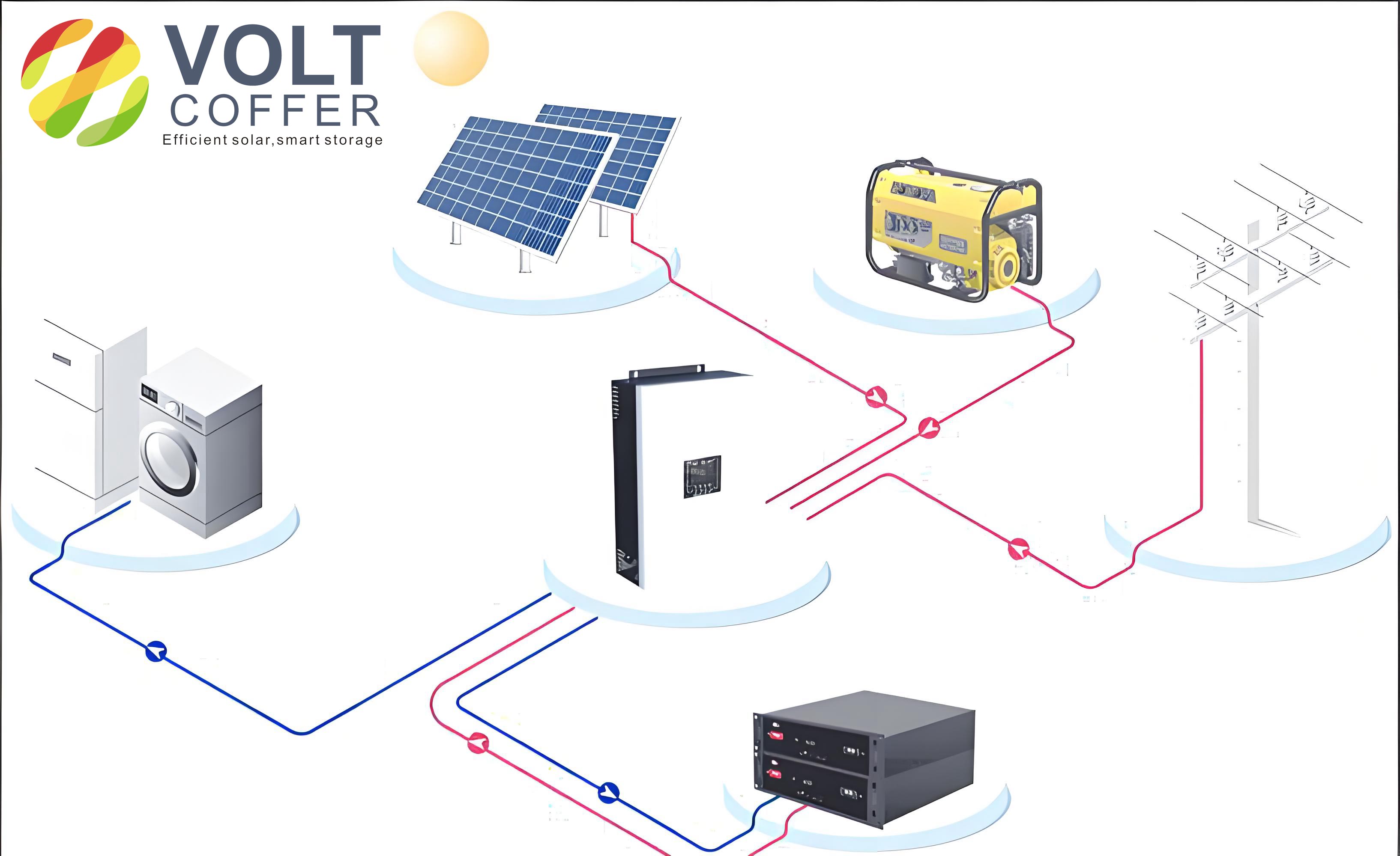
The core components of the off-grid solar system include PV panels, lithium-ion batteries, communication base station loads, and a power conversion system (PCS). The PCS employs a multi-stage conversion architecture: PV panels are connected to a common DC bus via a unidirectional DC-DC boost converter, while lithium-ion batteries interface with the same bus through a bidirectional buck-boost DC-DC converter. A unified full-bridge inverter, also connected to the DC bus, converts DC power to AC for supplying the loads. This topology allows flexible energy management, enabling the system to operate efficiently across different scenarios, such as sunny periods, nights, or cloudy days. The off-grid solar system is particularly suited for remote applications due to its scalability, low maintenance requirements, and ability to function independently of the grid.
The operational modes of the off-grid solar system are defined based on the energy availability from PV panels and the state of charge (SOC) of the batteries. Specifically, the system can transition between four primary operational conditions: (1) PV energy is available, and batteries are not overcharged; (2) PV energy is available, but batteries are overcharged or charging power is excessive; (3) PV energy is unavailable, but batteries have sufficient charge; and (4) both PV energy and battery charge are insufficient, leading to system shutdown. Each condition requires distinct control strategies for the converters to maintain stability and efficiency. For instance, in Condition 1, the PV-side boost converter operates in maximum power point tracking (MPPT) mode to extract maximum solar energy, while the battery-side bidirectional converter works in boost mode to regulate the DC bus voltage. This ensures that the load is powered primarily by PV energy, with any excess used to charge the batteries or any deficit supplemented by battery discharge.
To mathematically model the MPPT operation for the PV-side boost converter, the perturb and observe (P&O) algorithm is employed. This method adjusts the duty cycle of the converter to maximize power output by periodically perturbing the operating point and observing the change in power. The power from the PV panels can be expressed as:
$$ P_{pv} = V_{pv} \times I_{pv} $$
where \( P_{pv} \) is the PV power, \( V_{pv} \) is the PV voltage, and \( I_{pv} \) is the PV current. The P&O algorithm updates the duty cycle \( D \) based on the power gradient:
$$ D_{k+1} = D_k + \Delta D \cdot \text{sign}\left( \frac{\Delta P_{pv}}{\Delta V_{pv}} \right) $$
Here, \( \Delta D \) is the perturbation step size, and \( \text{sign} \) function determines the direction of adjustment. This approach ensures that the off-grid solar system operates near the maximum power point under varying irradiance conditions, enhancing overall energy yield.
For the battery-side bidirectional buck-boost converter, the control strategy depends on the system condition. When regulating the DC bus voltage in boost mode, a dual-loop control structure is used, with an outer voltage loop and an inner current loop. The voltage error \( e_v \) between the reference DC bus voltage \( V_{dc,ref} \) and the measured value \( V_{dc} \) is processed by a proportional-integral (PI) controller:
$$ e_v = V_{dc,ref} – V_{dc} $$
$$ I_{bat,ref} = K_{p,v} e_v + K_{i,v} \int e_v \, dt $$
where \( I_{bat,ref} \) is the reference battery current, and \( K_{p,v} \) and \( K_{i,v} \) are the PI gains. The inner current loop then adjusts the converter switching to track this reference. In buck mode, during battery charging, a similar dual-loop control maintains the battery voltage or current within safe limits, preventing overcharging. The battery voltage dynamics can be described as:
$$ V_{bat} = \frac{1}{C_{bat}} \int I_{bat} \, dt + R_{bat} I_{bat} $$
where \( C_{bat} \) is the battery capacitance, and \( R_{bat} \) is the internal resistance. This ensures efficient energy storage management in the off-grid solar system.
The inverter control for the load side employs a bipolar modulation scheme for the full-bridge inverter to minimize common-mode currents, which is crucial for safety and electromagnetic compatibility. The output AC voltage \( V_{ac} \) is regulated using a sinusoidal pulse width modulation (SPWM) technique, with the modulation index \( m_a \) defined as:
$$ m_a = \frac{V_{control}}{V_{tri}} $$
where \( V_{control} \) is the control voltage from the feedback loop, and \( V_{tri} \) is the peak triangular carrier voltage. The output voltage is then:
$$ V_{ac} = m_a \cdot \frac{V_{dc}}{2} \cdot \sin(\omega t) $$
with \( \omega = 2\pi f \) and \( f = 50\, \text{Hz} \). This ensures a stable 220 V AC supply for the communication loads, integral to the off-grid solar system’s functionality.
The energy management strategy for the off-grid solar system is implemented using a state machine approach, which transitions between states based on predefined events. These events are derived from system variables such as PV voltage, battery voltage, battery current, and DC bus voltage. The state machine ensures robust and automatic operation, adapting to changes in energy availability and load demand. Below is a table summarizing the key events that trigger state transitions:
| Event Number | Event Description |
|---|---|
| 0 | System start command |
| 1 | PV energy available and battery not overcharged |
| 2 | PV energy available and battery overcharged |
| 3 | PV energy unavailable and battery not over-discharged |
| 4 | PV energy unavailable and battery over-discharged |
| 5 | Battery charging power excessive or battery overcharged |
| 6 | DC bus voltage drop with PV energy available |
| 7 | DC bus voltage drop with PV energy unavailable |
| 8 | PV energy available |
| 9 | Battery over-discharged |
| 10 | PV energy unavailable |
| 11 | Fault or system stop command |
The state diagram for the energy management of the off-grid solar system includes states such as Standby, Condition 1, Condition 2, Condition 3, and Shutdown. For example, from the Standby state, if Event 1 occurs (PV energy available and battery not overcharged), the system transitions to Condition 1, where the PV converter operates in MPPT mode and the battery converter in boost mode. If Event 2 is detected (PV energy available but battery overcharged), it moves to Condition 2, switching the PV converter to constant voltage mode and the battery converter to buck mode for controlled charging. This dynamic state management ensures that the off-grid solar system prioritizes PV energy usage while safeguarding battery health.
In practical implementation, the off-grid solar system was tested with a 5 kW PV array, lithium-ion batteries with a voltage range of 192 V to 208 V, and a 2 kW load. The DC bus voltage was maintained at 480 V, and the system demonstrated seamless transitions between operational conditions. Experimental results showed that during Condition 1, the PV panels delivered up to 4 kW of power, with 2 kW supplying the load and 2 kW charging the batteries. The battery charging current was regulated at 10 A, and the DC bus voltage remained stable, confirming the effectiveness of the control strategies. The off-grid solar system’s ability to handle varying scenarios underscores its suitability for remote communication base stations, where energy reliability is paramount.
Further analysis of the off-grid solar system involves evaluating efficiency metrics, such as the overall system efficiency \( \eta \), which accounts for losses in converters and batteries. This can be expressed as:
$$ \eta = \frac{P_{load}}{P_{pv} + P_{bat}} \times 100\% $$
where \( P_{load} \) is the load power, \( P_{pv} \) is the PV power input, and \( P_{bat} \) is the battery power (positive for discharging, negative for charging). In our tests, the off-grid solar system achieved efficiencies above 90% under optimal conditions, highlighting the benefits of the proposed energy management approach.
Another critical aspect is the battery lifecycle management in the off-grid solar system. Lithium-ion batteries are sensitive to overcharging and deep discharging, which can reduce their lifespan. The control strategy incorporates voltage and current limits to prevent such issues. For instance, the battery charging current \( I_{chg} \) is constrained by:
$$ I_{chg} \leq I_{chg,max} $$
where \( I_{chg,max} = 10\, \text{A} \) in our setup. Similarly, the battery voltage \( V_{bat} \) is kept within safe bounds:
$$ V_{bat,min} \leq V_{bat} \leq V_{bat,max} $$
with \( V_{bat,min} = 192\, \text{V} \) and \( V_{bat,max} = 208\, \text{V} \). This proactive management extends battery life, reducing maintenance costs for the off-grid solar system in remote locations.
The inverter’s performance in the off-grid solar system is also crucial for power quality. Total harmonic distortion (THD) of the output voltage is minimized through the bipolar modulation scheme. The THD is defined as:
$$ \text{THD} = \frac{\sqrt{\sum_{h=2}^{\infty} V_h^2}}{V_1} \times 100\% $$
where \( V_h \) is the harmonic voltage component, and \( V_1 \) is the fundamental component. Measurements indicated a THD below 5%, meeting standards for telecommunication equipment. This ensures that the off-grid solar system provides clean and stable power, essential for sensitive communication devices.
In summary, the energy management control strategy for off-grid solar systems in remote communication base stations effectively coordinates multiple power converters to optimize energy utilization. By leveraging state-based transitions and advanced control algorithms, the system adapts to environmental changes, maximizes solar energy harvesting, and ensures reliable power supply. Experimental validation on a 5 kW prototype confirms the strategy’s robustness, with efficient operation across various conditions. The off-grid solar system represents a sustainable solution for powering isolated infrastructure, contributing to the expansion of telecommunication networks in underserved areas. Future work could explore integration with other renewable sources or smart grid technologies to further enhance the off-grid solar system’s capabilities.