
0. Introduction
Traditional diesel-powered workover rigs face challenges including high energy consumption, excessive noise, and environmental pollution. In contrast, LiFePO4 battery-powered electric workover rigs demonstrate superior energy efficiency, reduced noise levels, and zero emissions. This paper explores the technical implementation of LiFePO4 battery energy storage systems in overcoming grid capacity limitations while maintaining operational efficiency in oilfield applications.
1. System Design Requirements
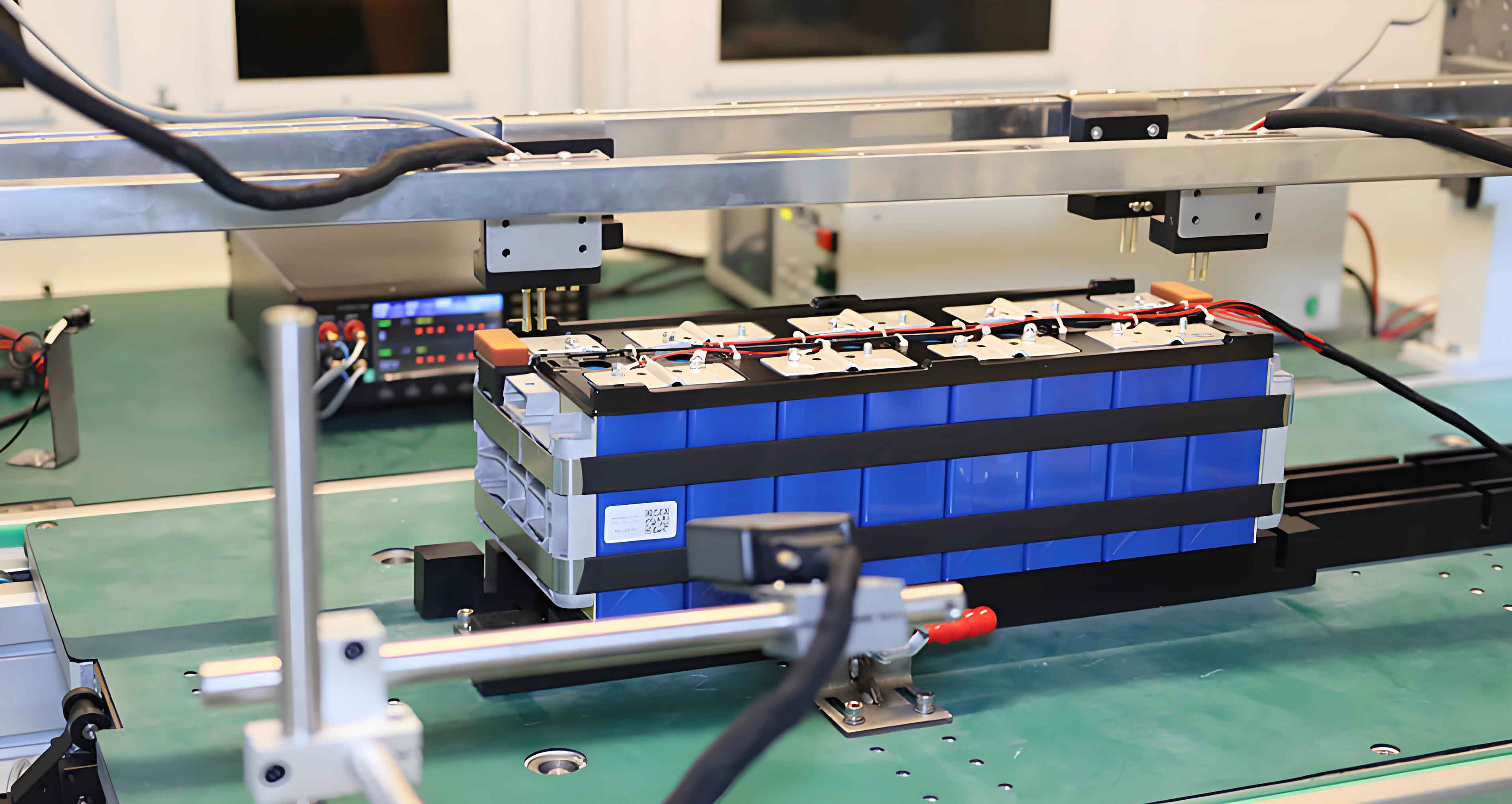
The LiFePO4 battery energy storage system comprises modular PACK battery units, battery management system (BMS), power conversion systems, and thermal management components. Key operational parameters include:
- Continuous discharge current: 300 A
- Peak current (20s): 450 A
- Operating voltage range: 320-384 VDC
The energy density (Ed) of LiFePO4 batteries is calculated as:
$$E_d = \frac{C \times V}{m}$$
Where C = battery capacity (Ah), V = nominal voltage (V), and m = battery mass (kg).
2. Energy Storage System Configuration
2.1 Workover Operational Characteristics
Typical workover operations exhibit intermittent power demand patterns as shown in Table 1:
| Operation Phase | Duration (s) | Power Demand (kW) |
|---|---|---|
| Pipe lifting | 20 | 150-200 |
| Thread handling | 10 | 30-50 |
| Pipe lowering | 15 | 80-120 |
This cyclical operation enables optimized energy utilization through LiFePO4 battery’s rapid charge-discharge capabilities.
2.2 Battery Selection Analysis
Comparative analysis of battery technologies reveals LiFePO4’s advantages:
| Parameter | LiFePO4 | NMC | Lead-Carbon |
|---|---|---|---|
| Cycle Life | >6,000 | 3,000 | 1,500 |
| Energy Density (Wh/kg) | 120-160 | 150-220 | 30-50 |
| Thermal Range (°C) | -20 to 55 | 15 to 35 | -20 to 50 |
| Safety | Excellent | Moderate | Good |
2.3 Battery Management System Architecture
The BMS ensures safe operation through:
- Cell voltage monitoring: ±1 mV accuracy
- Temperature sensing: ±0.5°C precision
- State-of-Charge (SOC) estimation using Coulomb counting:
$$SOC(t) = SOC_0 – \frac{1}{C_n} \int_{0}^{t} \eta I(\tau) d\tau$$
Where Cn = nominal capacity, η = coulombic efficiency, and I = current.
3. Power Management Strategy
The hybrid power supply system combines grid power (Pgrid) and LiFePO4 battery output (Pbat) to meet load demand (Pload):
$$P_{load} = P_{grid} + P_{bat}$$
Charge/discharge efficiency (ηsys) is calculated as:
$$\eta_{sys} = \frac{E_{discharge}}{E_{charge}} \times 100\%$$
Typical system efficiencies reach 92-95% for LiFePO4 systems.
4. Thermal Management System
The liquid-cooled thermal management system maintains optimal operating temperatures (15-35°C) through:
- Cooling capacity: 3-5 kW per battery module
- Heating power density: 0.5 W/cm²
- Temperature uniformity: <5°C difference across cells
5. Field Test Results
Field trials demonstrated:
| Parameter | Performance |
|---|---|
| Total operation time | 8 hours |
| Energy consumption | 264 kWh |
| Grid contribution | 220 kWh (83.3%) |
| Battery contribution | 44 kWh (16.7%) |
| Peak power delivery | 180 kW |
6. Conclusion
The LiFePO4 battery energy storage system successfully addresses the power limitations of conventional electric workover rigs, demonstrating:
- 35% reduction in energy costs compared to diesel systems
- 72 dB noise reduction versus conventional rigs
- Zero direct emissions during operation
This technology establishes a foundation for broader application of LiFePO4 batteries in oilfield equipment, with potential extensions to drilling systems and hybrid power solutions.