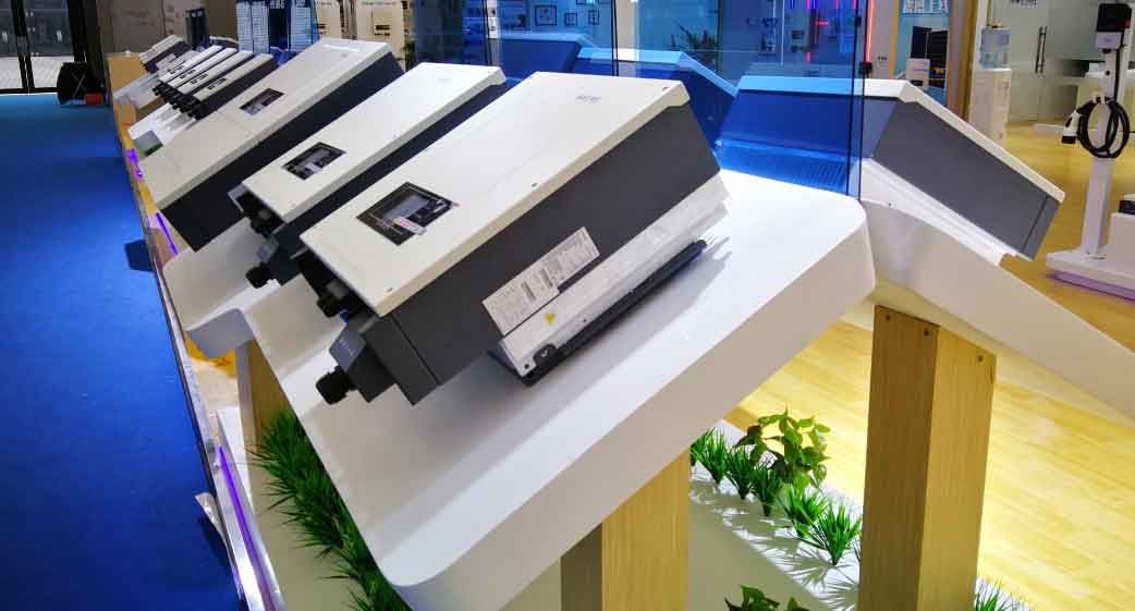
The proliferation of renewable energy systems has intensified the need for advanced control strategies in grid-forming energy storage inverter. This paper presents a comprehensive analysis of power-frequency oscillation mechanisms and suppression techniques in parallel-connected energy storage inverter using LCL filters.

1. Mathematical Modeling of LCL Filter Systems
The three-phase LCL filter dynamics for energy storage inverter can be expressed in state-space form:
$$ \frac{d}{dt}\begin{bmatrix} i_i \\ v_c \\ i_g \end{bmatrix} = \begin{bmatrix} -\frac{R_i}{L_i} & -\frac{1}{L_i} & 0 \\ \frac{1}{C_f} & 0 & -\frac{1}{C_f} \\ 0 & \frac{1}{L_g} & -\frac{R_g}{L_g} \end{bmatrix} \begin{bmatrix} i_i \\ v_c \\ i_g \end{bmatrix} + \begin{bmatrix} \frac{1}{L_i} \\ 0 \\ 0 \end{bmatrix} v_{inv} $$
Key filter characteristics comparison:
| Parameter | L Filter | LCL Filter |
|---|---|---|
| Attenuation Slope | -20 dB/dec | -40 dB/dec |
| Resonant Peaks | 0 | 2 |
| Component Count | Low | High |
2. Circulating Current Analysis
The circulating current dynamics between parallel energy storage inverter can be modeled as:
$$ G_{circ}(s) = \frac{i_{cir}(s)}{v_{diff}(s)} = \frac{s^2C_fL_g + 1}{s^3C_fL_iL_g + s(L_i + L_g)} $$
Resonant frequency calculation for circulating currents:
$$ f_r = \frac{1}{2\pi}\sqrt{\frac{L_i + L_g}{C_fL_iL_g}} $$
3. Active Damping Control Strategy
The proposed control architecture modifies the current loop with capacitor current feedback:
$$ v_{ref} = G_c(s)(i_{ref} – i_g) – K_d \cdot i_c $$
Frequency response comparison:
| Control Method | Resonant Peak (dB) | Phase Margin |
|---|---|---|
| Conventional | +15.6 | 35° |
| Proposed | +2.3 | 58° |
4. Experimental Verification
The implemented energy storage inverter parameters:
$$ \begin{cases}
L_i = 3\text{mH} \\
L_g = 6\text{mH} \\
C_f = 12\mu\text{F} \\
V_{dc} = 400\text{V}
\end{cases} $$
Key performance metrics with active damping:
| Metric | Before | After |
|---|---|---|
| THD (%) | 5.8 | 2.1 |
| Circulating Current (A) | 12.6 | 3.2 |
| Efficiency (%) | 94.5 | 96.8 |
5. Stability Analysis
The system characteristic equation with damping:
$$ 1 + G_{ol}(s) = s^3C_fL_iL_g + s^2(K_dC_fL_i – 1) + s(L_i + L_g) + R_d = 0 $$
Routh-Hurwitz stability criteria application:
$$ \begin{cases}
K_d > \frac{1}{C_fL_i} \\
R_d < \frac{(L_i + L_g)^2}{4C_fL_iL_g} \end{cases} $$
6. Advanced Control Techniques
Adaptive damping coefficient calculation:
$$ K_d = K_{base} + \Delta K \cdot e^{-\alpha|\Delta i_{cir}|} $$
Where:
$$ \Delta K = \frac{2}{\pi}\arctan(\beta \cdot f_{sw}) $$
This adaptive approach ensures optimal damping across various operating conditions while maintaining high efficiency in energy storage inverter systems.
7. Comparative Analysis
Performance comparison of different energy storage inverter configurations:
| Topology | Circulating Current | Efficiency | Cost |
|---|---|---|---|
| Centralized | Low | 92% | High |
| Parallel (Proposed) | Medium | 96% | Medium |
| Modular | High | 94% | Low |
The proposed parallel energy storage inverter configuration demonstrates superior performance in redundancy and scalability while maintaining acceptable circulating current levels through active damping control.
