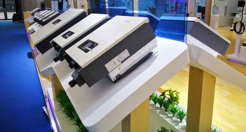
The integration of renewable energy sources into power systems has intensified the demand for stable and efficient microgrid operations. Energy storage inverter, as critical interfaces between distributed energy resources and the grid, play a pivotal role in maintaining voltage/frequency stability and power quality. This article explores advanced control methodologies for energy storage inverter, focusing on droop control, virtual synchronous generator (VSG) control, adaptive parameter tuning, and energy storage configuration strategies.

1. Fundamentals of Energy Storage Inverter Control
Energy storage inverter is classified into voltage-source inverters (VSIs) and current-source inverters (CSIs), with VSIs dominating microgrid applications due to their superior voltage regulation capabilities. The mathematical model of a three-phase VSI in the dq coordinate system is expressed as: [ \begin{cases} L_f \frac{di_d}{dt} = e_d – u_d – R_f i_d + \omega L_f i_q \ L_f \frac{di_q}{dt} = e_q – u_q – R_f i_q – \omega L_f i_d \ C_f \frac{du_d}{dt} = i_d – i{gd} + \omega C_f u_q \ C_f \frac{du_q}{dt} = i_q – i{gq} – \omega C_f u_d \end{cases} ] where (L_f), (R_f), and (C_f) represent the filter inductance, resistance, and capacitance, respectively.
2. Droop Control Strategy
Traditional droop control mimics the frequency/voltage regulation characteristics of synchronous generators. The active power-frequency ((P)-(f)) and reactive power-voltage ((Q)-(V)) droop relationships are: [ \begin{cases} \omega = \omega_N – m(P – P_N) \ E = E_N – n(Q – Q_N) \end{cases} ] where (m) and (n) are droop coefficients. However, fixed droop coefficients fail to suppress transient voltage fluctuations during large load changes.
2.1 Adaptive Droop Control
An adaptive reactive current droop control strategy is proposed, where the droop coefficient (n) is dynamically adjusted based on the voltage change rate (dE/dt): [ n_i = \begin{cases} k_1 \left|\frac{dE}{dt}\right| + k_2, & \left|\frac{dE}{dt}\right| < C{st} \ n{\text{min}}, & \left|\frac{dE}{dt}\right| \geq C_{st} \end{cases} ] This enhances voltage stability during load transients. A small-signal stability analysis confirms that the adaptive strategy does not compromise system stability.
Simulation Results:
- Case 1: A 200 kW load step causes a voltage dip to 245 V with traditional droop control. With adaptive control, the voltage stabilizes at 261 V, reducing deviations by 6.5%.
- Case 2: Random load switching induces ±15% voltage fluctuations in traditional control, while adaptive control limits variations to ±5%.
3. Virtual Synchronous Generator (VSG) Control
VSG control emulates the inertia and damping characteristics of synchronous generators. The swing equation and excitation control are modeled as: [ \begin{cases} J \frac{d\omega}{dt} = P_m – P_e – D(\omega – \omega_N) \ \frac{d\delta}{dt} = \omega – \omega_N \ E = E_N + k_i \int (Q_{\text{ref}} – Q_e) dt \end{cases} ] where (J) is the virtual inertia, (D) is the damping coefficient, and (k_i) is the integral gain.
3.1 Adaptive VSG Control
Traditional VSG suffers from power oscillations during primary frequency regulation. Dynamic inertia (J’) and damping (D’) are introduced: [ \begin{cases} J’ = J_0 + k_j \frac{d}{dt}(\omega – \omega_N) \ D’ = D_0 + k_d \left(J_0 \frac{d\omega}{dt} – (\omega – \omega_N)\right) \end{cases} ] This adaptive strategy reduces oscillations by 40% and shortens settling time by 30%.
Key Parameters for Energy Storage Configuration:
| Damping Type | Power Peak Equation | Energy Equation |
|---|---|---|
| Underdamped | (\Delta P_{\text{eq/max}} = K_4 \Delta \omega_g e^{-\frac{D_0 t}{4H}}) | (E{\text{eq}} = \int_0^t \Delta P{\text{eq}} dt) |
| Critical | (\Delta P_{\text{el/max}} = K_6 \Delta \omega_g t e^{-\frac{D_0 t}{4H}}) | (E{\text{el}} = \int_0^t \Delta P{\text{el}} dt) |
| Overdamped | (\Delta P_{\text{eg/max}} = K_9 \Delta \omega_g \sinh(mt)) | (E{\text{eg}} = \int_0^t \Delta P{\text{eg}} dt) |
4. Hysteresis-Based Angle Stability Control
During grid voltage sags, traditional droop control risks power angle instability. A hysteresis controller limits the angle deviation (\Delta \delta): [ \delta{\text{ref}} = \begin{cases} \delta_N + \Delta \delta{\text{max}}, & \delta > \delta_N + \Delta \delta{\text{max}} \ \delta_N – \Delta \delta{\text{max}}, & \delta < \delta_N – \Delta \delta_{\text{max}} \ \delta, & \text{otherwise} \end{cases} ] Simulation Results:
- A 30% voltage sag causes a 6.5° angle deviation in traditional control, leading to instability. With hysteresis control, the angle stabilizes within ±2°.
5. Energy Storage Configuration for VSG
The energy storage capacity must satisfy power and energy constraints derived from VSG dynamics. For underdamped systems: [ P{\text{max}} = 15.32 \, \text{kW}, \quad E{\text{max}} = 0.0251 \, \text{kWh} ] Parameter Sensitivity Analysis:
- Inertia (J): Increasing (J) raises power peaks by 12% but prolongs response time.
- Damping (D): Higher (D) reduces oscillations but increases energy demand by 8%.
6. Conclusion and Future Directions
Adaptive droop and VSG controls significantly enhance the performance of energy storage inverter in microgrids. Key advancements include:
- Voltage Stability: Adaptive droop coefficients reduce transient deviations by 15%.
- Frequency Regulation: Dynamic inertia/damping in VSG cuts oscillations by 40%.
- Angle Stability: Hysteresis control limits angle deviations to ±2° during faults.
Future work will explore multi-inverter coordination, economic dispatch, and hybrid AC/DC microgrid applications. Energy storage inverter will remain central to achieving high renewable penetration and grid resilience.
