
In order to verify the rationality of the previous chapters and to better understand the working principle of grid connected solar inverters, a 2000W experimental prototype was developed. The actual pictures of the prototype, debugging precautions, and experimental waveforms of the quasi proportional resonant current control strategy were provided.
| Bus input voltage | 380V |
| Output filtering inductance | 2.52mH |
| Output filtering capacitor | 4.7μF |
| Grid connected current | 10A (effective value) |
| Grid voltage | 220V (effective value) |
| Carrier frequency | 20kHz |
The prototype parameters are shown in the table.
1. Precautions during debugging
The steps to debug the TMS320F28035 control board are as follows:
Use circuit simulation software SIMetrix to simulate the sampling circuit on the control board, obtain the theoretical sampling values of the sampling circuit, and help analyze the actual circuit.
Check the voltage on the control board. First, confirm whether the 5V and 3.3V power supplies are normal, and then determine whether the sampling signals of voltage and current exceed the range of 0-3.3V. Only after everything is normal can the sampling signals be connected to the corresponding pins of the control chip.
In the debugging process of the current control loop, first use MATLAB tools to theoretically verify the current control strategy, then use TI debugging tool CCS5.0, and combine oscilloscope observation of sampling signals and control signals for debugging. Finally, complete the grid connection function. The following are the points to pay attention to in actual debugging:
First, verify the mains sampling signal, and then verify the digital phase-locked loop. Among them, the sampling value of the mains voltage and the digital phase-locked loop are verified by gradually increasing the mains voltage from 50V (effective value) to 220V (effective value).
First, verify the independent mode current control strategy of the grid connected solar inverter at a low voltage of 50V. If the experimental results are correct, then proceed with the grid connected experiment.
The idea in the grid connection experiment is as follows: start the grid connection from a low voltage of 50V (effective value of mains voltage) 2.5A (effective value of grid connected current), then perform 100V (effective value) 2.5A (effective value), then 150V (effective value) 2.5A (effective value), and finally perform 220V (effective value) 2.5A (effective value). When the voltage exceeds 150V, it is necessary to gradually increase the current for debugging: 2.5A (effective value), 3A (effective value), 5A (effective value), 8A (effective value), 10A (effective value), and finally debug the rated power.
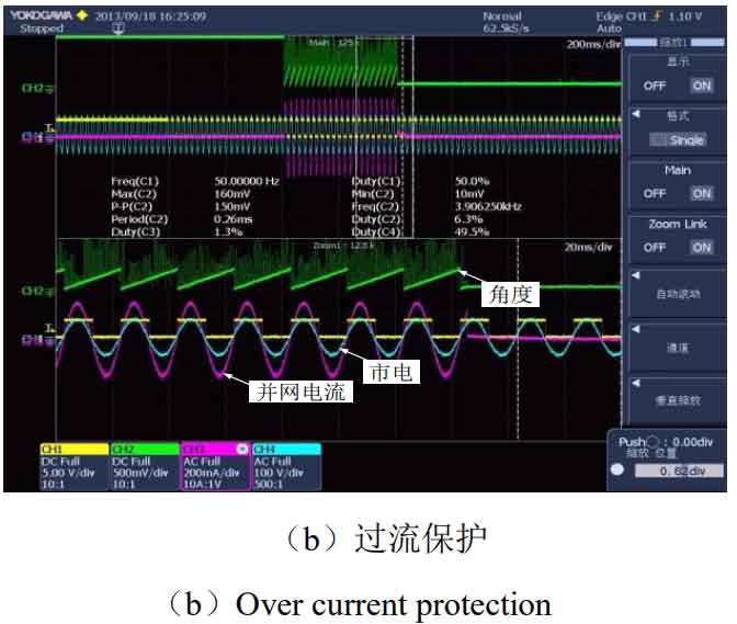
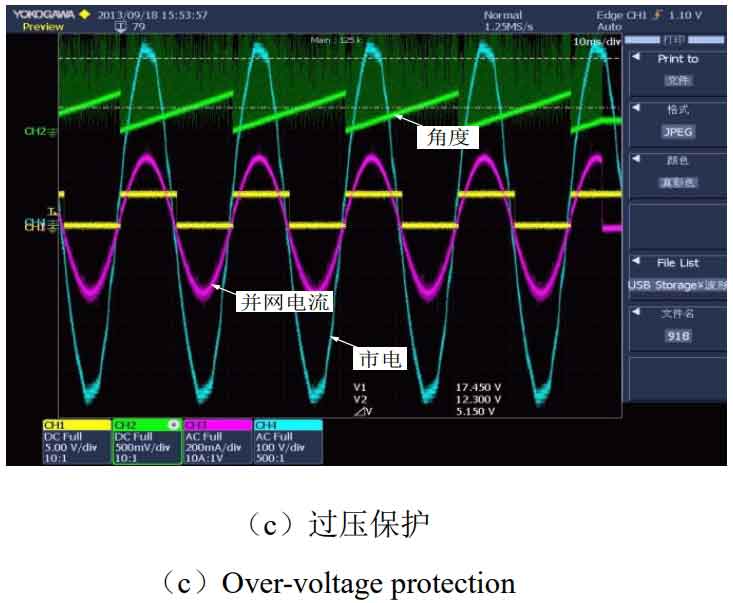
During the debugging process, some protective measures must be added, such as adding a manual emergency shutdown switch. If any abnormal situation is found during the experiment, the output of the solar inverter must be manually turned off immediately; 2. Add protective measures such as overvoltage/undervoltage, overcurrent/undervoltage frequency, and current ramp up control. Figure 3 shows the output of analog signals through the digital to analog conversion chip DAC7611, used to observe these important protection signals.
During the process of grid connection debugging, there are strict requirements for the power on sequence: first power on the busbar before going live; When the power is cut off, first turn off the drive signal output through the manual emergency switch, then disconnect the mains power, and finally disconnect the bus voltage.
Design steps for quasi PR controller parameters. By analyzing the Bode diagram of the open-loop transfer function, first determine the range of PR controller parameters, then optimize the controller parameters through Simulink simulation, and finally apply it to the experimental prototype to fine tune the parameters through experiments.
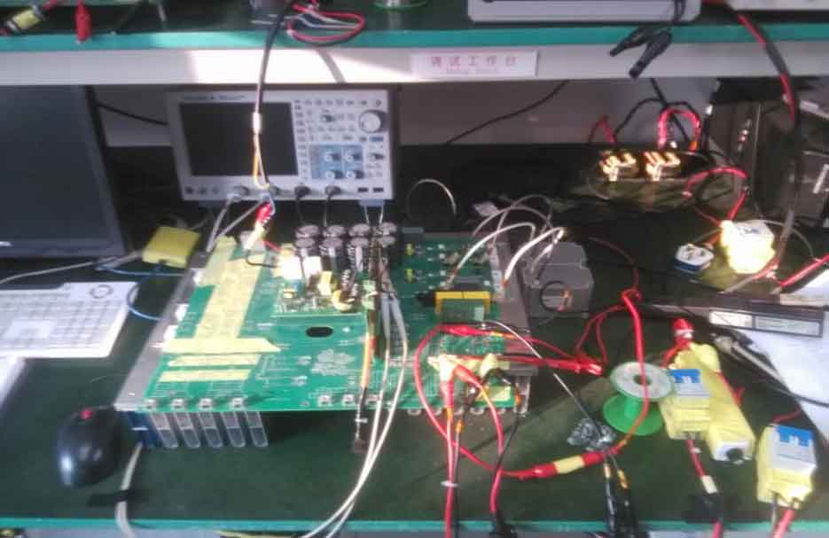
Figure 1 shows the physical prototype, and Figure 2 shows the physical control board.
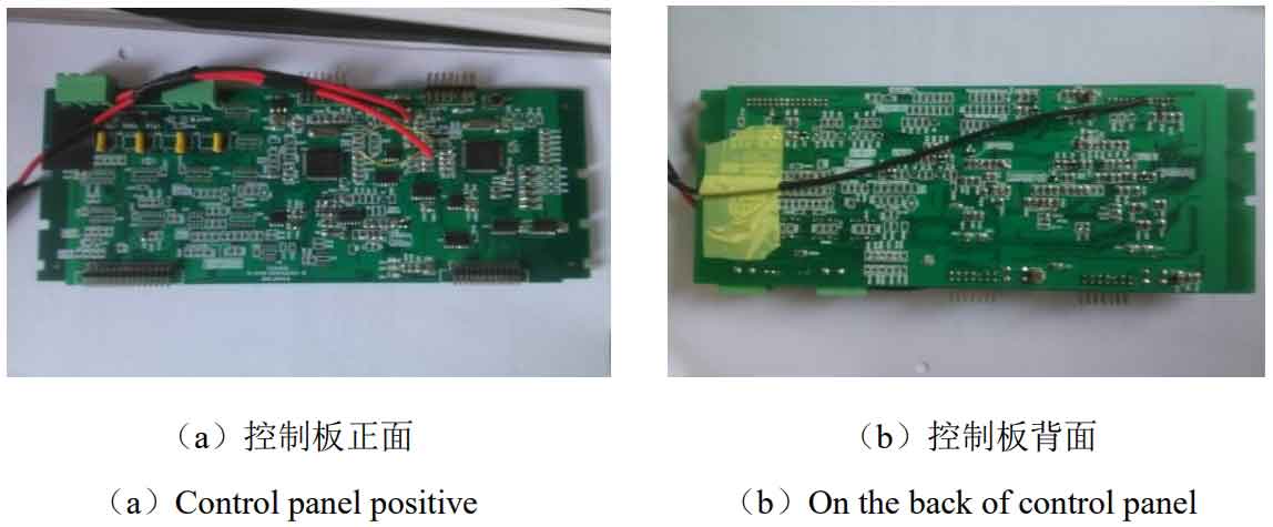
Figure 3 is a schematic diagram of various protection signals.
2. Experimental results
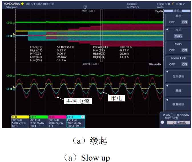
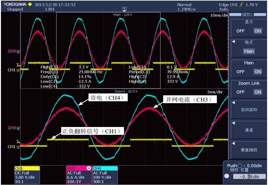
In the actual photovoltaic grid connection experiment, the control strategy adopted in this article is the quasi proportional resonant current control strategy, and the experimental results have achieved the expected experimental objectives. In Figure 4, Channel 4 measures the mains voltage signal (220V); Channel 3 measures the grid connected current waveform (9.5A); Channel 1 measures the positive and negative half axis reversal signal of the mains power supply. From Figure 4, it can be seen that the grid connected current is in the same frequency and phase as the mains voltage, and the current has a good output waveform, which meets the design requirements of the system.
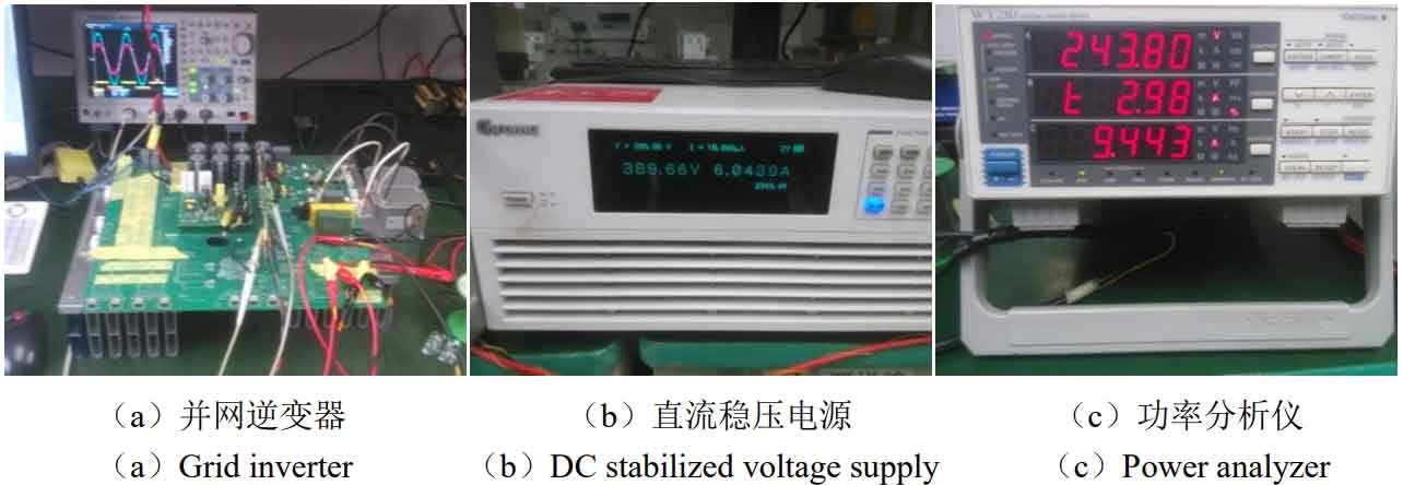
The physical image of the experimental prototype during grid connection operation is shown in Figure 5 (a). The figure (b) shows a digital DC power supply that provides a bus voltage of 380V. Figure (c) shows some parameters displayed by the power analyzer during operation: the output voltage of the solar inverter is 243.80V, the grid connected current is 9.443A, and the 2.98 displayed by the power analyzer refers to the total harmonic distortion (THD) of the grid connected current, which is 2.98%, meeting the design requirements of the project: THD<5% (in reality, THD fluctuates between 2.93% and 3.5%).
3. Summary
Due to the deterioration of human living environment and the arrival of energy crisis, solar energy as a new energy source has been widely concerned by people. Through in-depth theoretical analysis and experimental research on the phase-locked, current control strategy, DC component suppression, islanding detection and other issues of single-phase grid connected solar inverters in solar grid connected power generation systems, an experimental prototype of a single-phase solar grid connected inverter was made based on this. The main tasks are as follows:
Firstly, a detailed introduction was given to the principle of digital phase locking, and at the same time, a method for implementing digital control in the digital control chip TMS320F28035 was provided.
The principle of the quasi proportional resonant current control strategy was introduced, and a detailed theoretical analysis and controller parameter design were provided. In addition, a method based on virtual capacitors was proposed to suppress the DC component in the grid connected current, which was verified by simulation and experiments.
In the detection of islanding effect, combined with the digital phase-locked characteristics of the system itself, islanding detection schemes for positive active frequency disturbance and negative active frequency disturbance are proposed, and verified through simulation.
During debugging, it was found that the integral part of the filtering circuit in the current sampling circuit cannot be too large, otherwise it will seriously affect the parameter adjustment of the current controller, resulting in distortion of the grid connected current waveform and failure to meet the grid connected requirements.
This project can also be improved in the following two aspects:
In digital control, as the control chip is fixed-point and does not support floating-point operations, it is necessary to use the IQMATH library function provided by TI company to perform floating-point operations, which will inevitably increase the computational load and processing time. Therefore, a floating-point chip can be considered. In the current control process, simple filtering processing should be performed on the sampled signal to reduce external environmental interference. There is still room for optimization of the controller parameters to reduce the fluctuation amplitude of THD.
In the detection of islanding effect, this article only verifies through simulation, while the actual prototype testing is only carried out in low voltage and pure resistive loads, only verifying that the islanding detection function can be achieved. In the future, work should be carried out to detect islanding effects under rated voltage (220V) combined with RLC load (with a quality factor of Q=2.5).